Driving mechanism support structure and control rod driving wire

A technology of driving mechanism and supporting structure, applied in the control of nuclear reaction, reducing greenhouse gas, climate sustainability, etc. The effect of solving thermal expansion problems and maintaining stability

Active Publication Date: 2020-11-20
TSINGHUA UNIV
View PDF4 Cites 1 Cited by
  • Summary
  • Abstract
  • Description
  • Claims
  • Application Information

AI Technical Summary

Problems solved by technology

[0004] The embodiment of the present invention provides a driving mechanism support structure and a control rod driving wire to solve the problem of unreasonable force on the hydraulic cylinder and the pin claw mechanism in the prior art when the driving mechanism is working

Method used


Image

  • Driving mechanism support structure and control rod driving wire
  • Driving mechanism support structure and control rod driving wire
  • Driving mechanism support structure and control rod driving wire

Examples


Embodiment Construction

[0037] In order to make the purpose, technical solutions and advantages of the embodiments of the present invention clearer, the technical solutions in the embodiments of the present invention will be clearly and completely described below in conjunction with the drawings in the embodiments of the present invention. Obviously, the described embodiments It is a part of embodiments of the present invention, but not all embodiments. Based on the embodiments of the present invention, all other embodiments obtained by persons of ordinary skill in the art without creative efforts fall within the protection scope of the present invention.

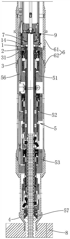
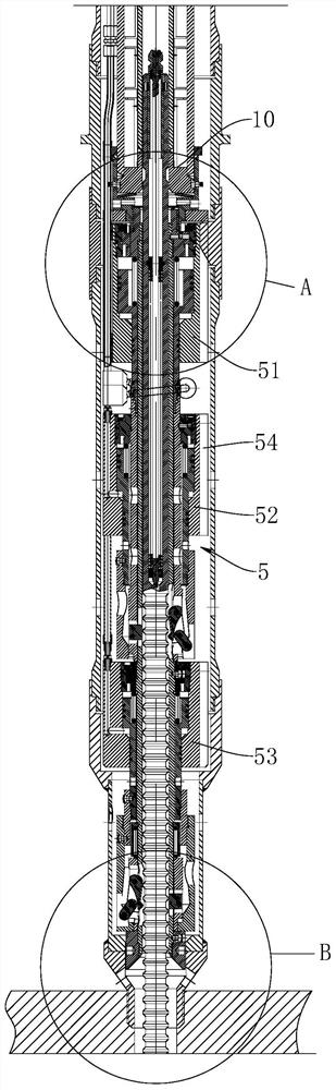
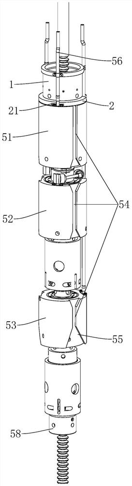
[0038] The supporting structure of the driving mechanism in the embodiment of the present invention is mainly applied to the control rod driving line for supporting and fixing the driving mechanism 5 . The driving mechanism 5 on the control rod driving line includes a lifting cylinder, a transfer cylinder, a clamping cylinder and a pin claw struct...


PUM


Abstract

The invention provides a driving mechanism support structure and a control rod driving wire. The driving mechanism support structure comprises a bearing piece, a supporting ring, a ring supporting piece and a lower end hole shrinkage piece, a supporting part is arranged on the inner wall of the annular supporting piece, the lower side of the supporting ring abuts against the supporting part, the upper side of the supporting ring abuts against the bearing piece, the lower portion of the bearing piece penetrates through a center hole of the supporting ring and is detachably connected with the upper end of the driving mechanism, and the upper end of the bearing piece abuts against a component which is arranged in the guide cylinder and is axially fixed, the upper end of the lower-end hole shrinkage piece is fixedly connected with the guide cylinder, the lower end is mounted on the reactor core supporting plate, the lower-end hole shrinkage piece sleeves the outer side of the lower end ofthe driving mechanism, and a gap is formed between the lower-end hole shrinkage piece and the lower end of the driving mechanism. Enough space is reserved for operation of the water pressure cylinderand the pin claw mechanism, the problem that the water pressure cylinder and the pin claw mechanism are unreasonable in stress in the working state is solved, a water diversion pipe of the driving mechanism is not interfered, and the performance and reliability of the driving mechanism are improved.

Description

technical field [0001] The invention relates to the technical field of nuclear reactor engineering, in particular to a driving mechanism support structure and a control rod driving line. Background technique [0002] Built-in control rod drive technology, the drive mechanism is placed in the high temperature, high pressure and irradiation environment in the reactor pressure vessel, and three hydraulic cylinders are used to drive, transfer, and clamp in sequence to move the two sets of pin claw mechanisms , to realize the step-up, step-down and drop functions of the control rod. [0003] Based on the working principle of the driving mechanism, the rationality of its supporting structure directly affects the working performance, service life and reliability of the driving mechanism. The support of the driving mechanism needs to meet the following requirements: in the process of work, the force is reasonable, and no additional force will be generated on the hydraulic cylinder ...

Claims


Application Information

Patent Timeline
Patent Type & Authority Applications(China)
IPC IPC(8): G21C7/12G21C7/16
CPCG21C7/12G21C7/16Y02E30/30
Inventor 薄涵亮王大中张作义秦本科赵陈儒王金海刘潜峰
Owner TSINGHUA UNIV
Why Eureka
Try Eureka