
Photovoltaic power supply system operating state detection method, device and terminal

A technology of power supply system and operating status, applied in the photovoltaic field, can solve the problems of inability to detect photovoltaic power supply system, increase maintenance cost, mismatch of load power consumption and backup power capacity, etc., so as to improve maintenance and repair efficiency, reduce maintenance cost, improve The effect of detection efficiency

Active Publication Date: 2022-06-07
CHINA TOWER CO LTD
View PDF0 Cites 0 Cited by
  • Summary
  • Abstract
  • Description
  • Claims
  • Application Information

AI Technical Summary

Problems solved by technology

[0002] The photovoltaic power supply system is the core system of the photovoltaic system. The common maintenance problems of the existing photovoltaic power supply system are mainly the insufficient effective capacity of the battery, the mismatch between the load power consumption and the power generation and backup capacity, and the setting of the charging current is too large or too small. The efficiency of the power generation system is low, and the performance of the backup power system (battery) deteriorates, etc.
The current common maintenance methods and fault diagnosis modes are carried out passively and blindly by maintenance personnel. Once a fault occurs, it needs to be checked and eliminated one by one. The troubleshooting efficiency is low, and the status and fault of the photovoltaic power supply system cannot be quickly and effectively analyzed. The detection greatly increases the maintenance cost, affects the normal production of the photovoltaic system, and reduces the working efficiency of the photovoltaic power supply system

Method used


Image

  • Photovoltaic power supply system operating state detection method, device and terminal
  • Photovoltaic power supply system operating state detection method, device and terminal
  • Photovoltaic power supply system operating state detection method, device and terminal

Examples


Embodiment Construction

[0049] The technical solutions in the embodiments of the present invention will be clearly and completely described below with reference to the accompanying drawings in the embodiments of the present invention. Obviously, the described embodiments are part of the embodiments of the present invention, but not all of the embodiments. Based on the embodiments of the present invention, all other embodiments obtained by those of ordinary skill in the art without creative efforts shall fall within the protection scope of the present invention.

[0050] Embodiments of the Invention The first invention provides a method for detecting an operating state of a photovoltaic power supply system.

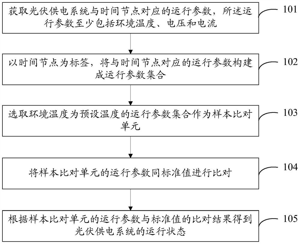
[0051] like figure 1 As shown, the first embodiment of the present invention provides a method for detecting an operating state of a photovoltaic power supply system, including S101 to S105.

[0052] S101: Acquire operating parameters of the photovoltaic power supply system corresponding to time...


PUM


Abstract

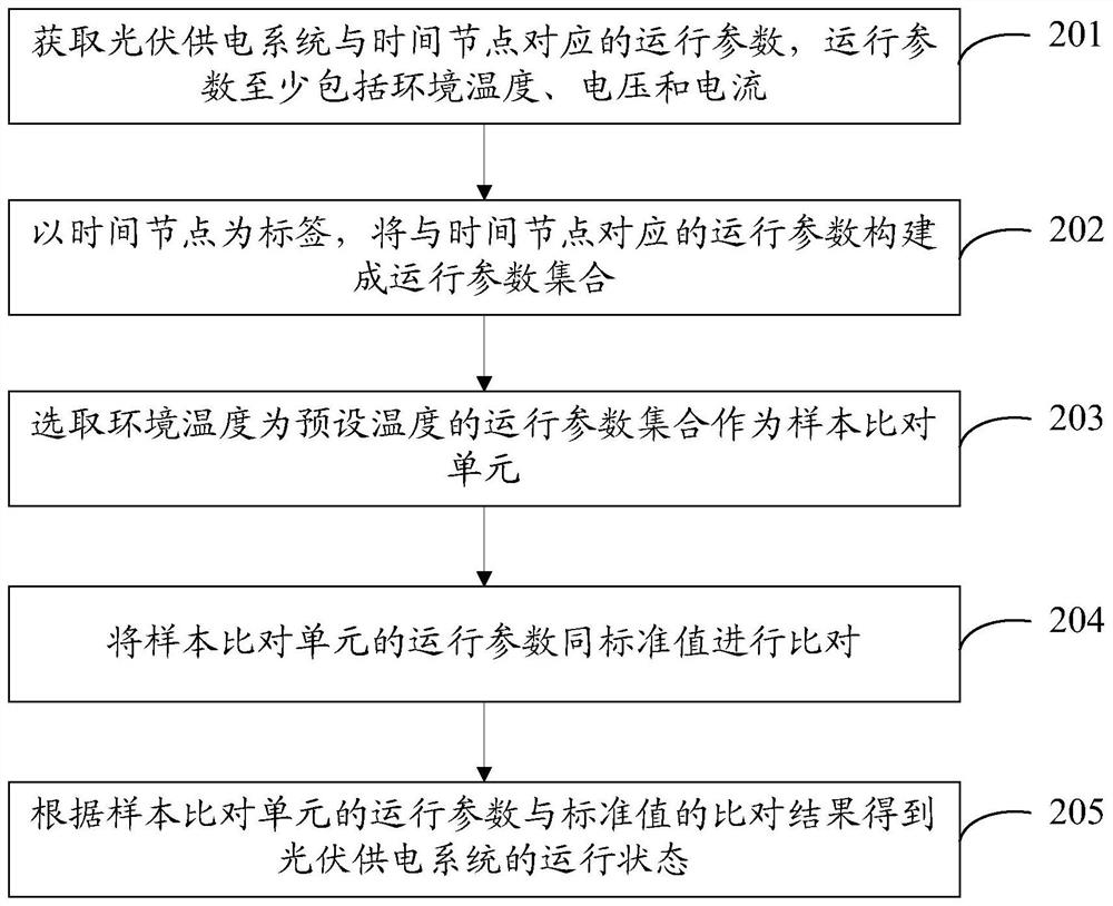
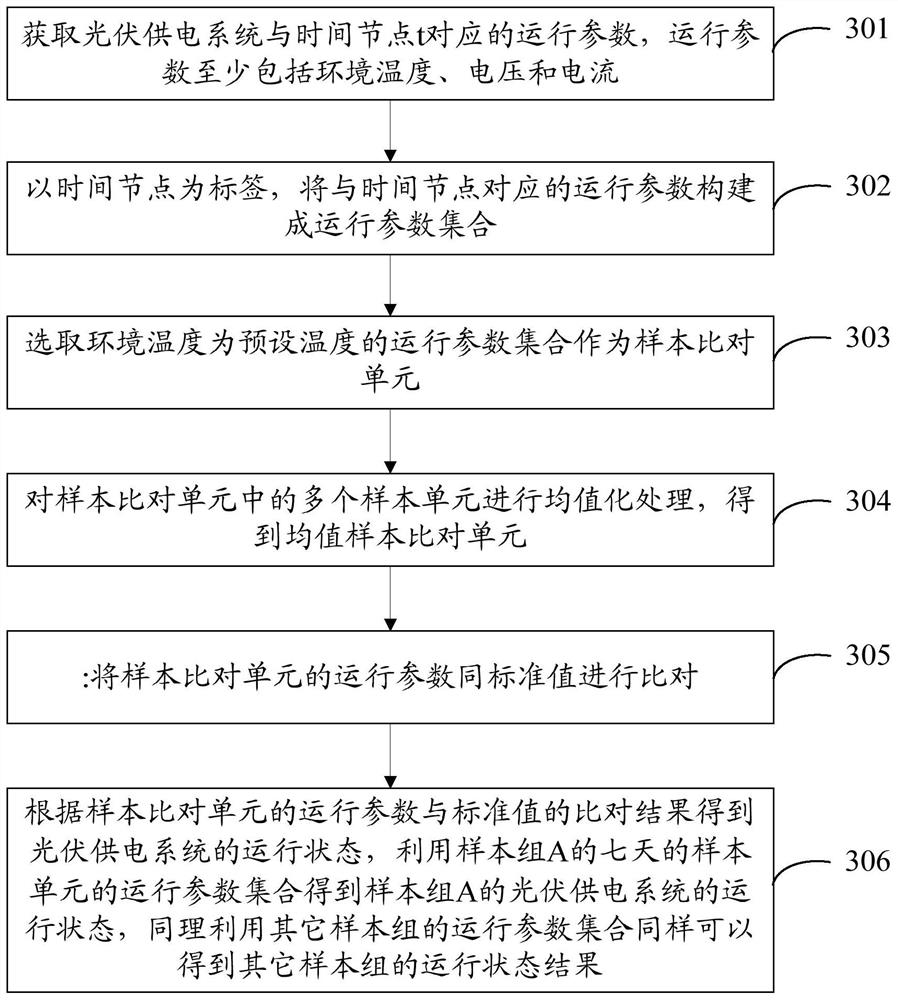
The present invention provides a method, device and terminal for detecting the operating state of a photovoltaic power supply system. The method includes: obtaining operating parameters corresponding to time nodes of the photovoltaic power supply system, the operating parameters at least including ambient temperature, voltage and current; The node is a label, and the operating parameters corresponding to the time nodes are constructed into an operating parameter set; the operating parameter set whose ambient temperature is a preset temperature is selected as a sample comparison unit; the sample comparison unit The operation parameters of the sample comparison unit are compared with the standard value; the operation status of the photovoltaic power supply system is obtained according to the comparison result of the operation parameter of the sample comparison unit and the standard value. The present invention changes the way of passively checking and determining the cause one by one into actively locating the cause of the problem, improves the efficiency of maintenance and repair, and reduces the maintenance cost.

Description

technical field [0001] The invention relates to the field of photovoltaics, in particular to a method, device and terminal for detecting the operating state of a photovoltaic power supply system. Background technique [0002] The photovoltaic power supply system is the core system of the photovoltaic system. The common maintenance problems of the existing photovoltaic power supply system are mainly insufficient effective capacity of the battery, the load power consumption does not match the power generation and backup power capacity, the charging current is set too large or too small, and the photovoltaic power supply is too large. The efficiency of the power generation system is low, and the performance of the backup power system (battery) is deteriorated. At present, the common maintenance methods and fault diagnosis modes are that the maintenance personnel are passive and blind. Once a fault occurs, it needs to be checked, confirmed and eliminated one by one. The efficien...

Claims


Application Information

Patent Timeline
Patent Type & Authority Patents(China)
IPC IPC(8): H02S50/00G06K9/62G06Q50/06
CPCH02S50/00G06Q50/06G06F18/22Y02E10/50
Inventor 赵瑞胜
Owner CHINA TOWER CO LTD
Learn More