
Fan track liner

A fan and track technology, applied in the field of fan track bushings

Active Publication Date: 2020-11-20
ROLLS ROYCE PLC
View PDF13 Cites 0 Cited by
  • Summary
  • Abstract
  • Description
  • Claims
  • Application Information

AI Technical Summary

Problems solved by technology

[0006] In particular, the containment means may be susceptible to being cut by, rather than crushed by, the metalwork of the fan blade in the event of a fan blade shedding

Method used


Image

  • Fan track liner
  • Fan track liner
  • Fan track liner

Examples


Embodiment Construction

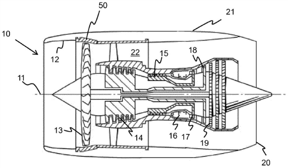
[0044] reference figure 1 , The gas turbine engine is generally represented by 10, and has a main axis and a rotation axis 11. The engine 10 includes an axially flowing air inlet 12, a propulsion fan 13, an intermediate pressure compressor 14, a high pressure compressor 15, a combustion device 16, a high pressure turbine 17, an intermediate pressure turbine 18, a low pressure turbine 19 and an exhaust nozzle 20. The nacelle 21 generally surrounds the engine 10 and defines an air inlet 12 and an exhaust nozzle 20.

[0045] The gas turbine engine 10 operates in a conventional manner so that the air entering the air inlet 12 is accelerated by the fan 13 to produce two air streams: the first air stream entering the intermediate pressure compressor 14 and the bypass duct 22 to provide propulsion The second air flow. Before sending the air to the high-pressure compressor 15 for further compression, the intermediate-pressure compressor 14 compresses the air flow directed therein.

[004...


PUM


Abstract

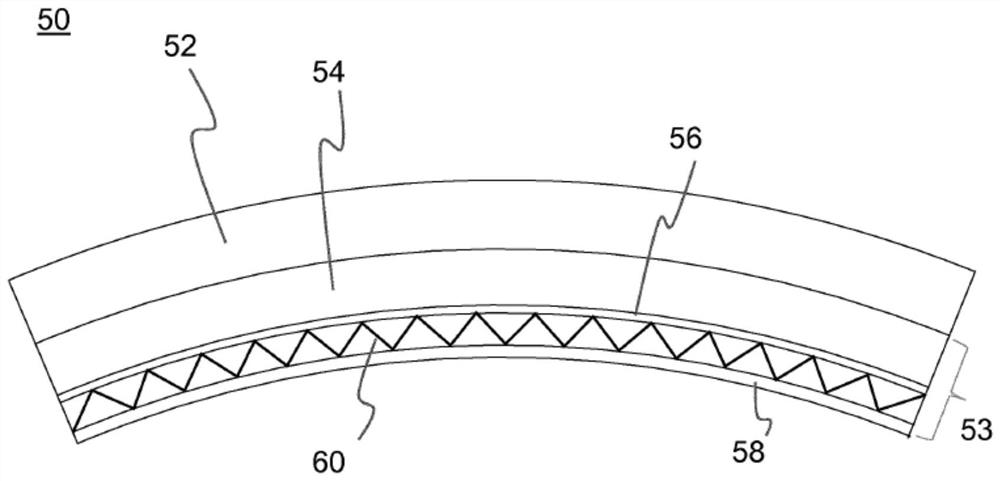
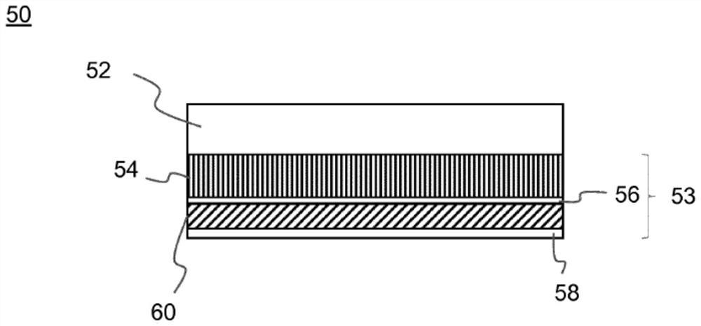
There is disclosed a fan track liner assembly (53) for a containment arrangement (50) of a gas turbine engine, the assembly (53) comprising a cellular reactive impact structure (60), wherein cells ofthe reactive impact structure (60) contain a reactive material having shear-thickening or shear-stiffening properties; whereby the reactive impact structure (60) is compliant during assembly to accommodate geometrical non-compliance in the fan track liner assembly.

Description

Technical field [0001] The invention relates to a fan track bushing. Background technique [0002] The known turbofan engine includes a fan facing the upstream end of the engine, the fan including a plurality of blades. Each fan blade is connected to the central fan disc, and in use is driven to rotate by the turbine stage of the corresponding engine. [0003] Generally, such engines include fan blade accommodations arranged circumferentially around the fan. In rare cases, for example, after a foreign object impacts, part or all of the fan blades fall off from the fan tray (fan blade fall-off event), a fan blade accommodation is provided to accommodate the fan blades. [0004] The known containment device includes a housing and a fan track bushing, the fan track bushing comprising a honeycomb material, such as an aluminum honeycomb. During a fan blade shedding event, the fan blade material will hit the honeycomb fan track bushing, and the honeycomb fan track bushing absorbs the en...

Claims


Application Information

Patent Timeline
IPC IPC(8): F01D21/04
CPCF05D2300/43F05D2300/702F05D2300/44F05D2250/183F01D21/045F05D2220/36F05D2230/60F05D2250/11F05D2250/23F05D2250/294F05D2300/501F05D2300/603F05D2300/612F05D2300/6031F05D2300/514F05D2250/283F05D2300/61F05D2300/48Y02T50/60F01D21/04F01D25/005F01D25/285
Inventor 史蒂文·M·霍尔
Owner ROLLS ROYCE PLC
Learn More