[0026] The technical solutions in the embodiments of the present invention will be clearly and completely described below with reference to the accompanying drawings in the embodiments of the present invention. Obviously, the described embodiments are only a part of the embodiments of the present invention, but not all of the embodiments.
[0027] In the description of the present invention, unless otherwise stated, "plurality" means two or more; the terms "upper", "lower", "left", "right", "inner", "outer" The orientation or positional relationship indicated by , "front end", "rear end", "head", "tail", etc. are based on the orientation or positional relationship shown in the accompanying drawings, and are only for the convenience of describing the present invention and simplifying the description, not Indicates or implies that the referred device or element must have a specific orientation, be constructed and operate in a specific orientation, and therefore should not be construed as a limitation of the invention, in addition, the terms "first", "second", "third", etc. For descriptive purposes only and should not be construed to indicate or imply relative importance.
[0028] In the description of the present invention, it should be noted that, unless otherwise expressly specified and limited, the terms "connected" and "connected" should be understood in a broad sense, for example, it may be a fixed connection, a detachable connection, or an integral connection. ground connection; it can be a mechanical connection or an electrical connection; it can be directly connected, or indirectly connected through an intermediate medium. .
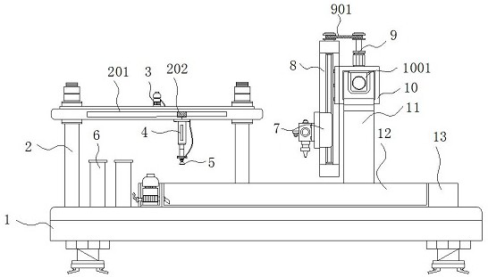
[0029] see Figure 1 to Figure 6, the present invention provides a technical solution: an LED light strip automatic assembly equipment with groove glue injection height detection, including a base 1, a workbench 13, a laser displacement sensor 20 and a U-shaped half sleeve 22, the top of the base 1 A frame body 2 is installed on one side, and a vacuum pump 3 is installed at the middle position of the top of the frame body 2. Electromagnetic slide rails 201 are provided at both ends of the top of the frame body 2, and sliders 202 are installed inside the electromagnetic slide rails 201. , the bottom end of the slider 202 is fixed with a hydraulic telescopic rod 4, and the bottom end of the hydraulic telescopic rod 4 is equipped with a vacuum suction cup 5, and the suction end of the vacuum pump 3 is connected with the suction end of the vacuum suction cup 5 through a hose, A placing box 6 is installed on the top of the base 1 under the frame body 2, and a workbench 13 is fixed at the middle position of the top of the base 1. A recovery pump 23 is installed inside the workbench 13 on the side close to the frame body 2, and the recovery pump 23 The input end is connected to the recovery glue tank 12 through the conduit, and the output end of the recovery pump 23 is connected to the top of the glue storage tank through the conduit. Reuse avoids waste of glue and is more practical.
[0030] A screw groove 1302 is opened at the middle position inside the worktable 13, and both ends of the screw groove 1302 are installed with a third screw 25. The shape of the screw groove 1302 is consistent with the bottom of the movable seat 27, and The length of the screw groove 1302 is 2.5 times the length of the movable seat 27. The matching design makes the movable seat 27 move more smoothly in the screw groove 1302, and is not easy to shake, which is convenient for the smooth progress of potting, and the 2.5 times design makes the movable seat 27 more smoothly. Each U-shaped semi-sleeve 22 on 27 can be moved to below the vacuum suction cup 5 and below the glue injection head 21, so that the material feeding and potting are smoother and the design is more reasonable.
[0031] A servo motor 26 is installed on the side of the worktable 13 away from the frame body 2, and the output end of the servomotor 26 is connected to the third screw rod 25 through the sprocket mechanism 2601. Both ends of the worktable 13 are provided with recycling glue grooves. 12, and the worktable 13 between the recovery glue groove 12 and the screw groove 1302 is provided with a ball groove 1301, a movable seat 27 is installed inside the worktable 13, and the limit plate 24 is fixed on the top of the movable seat 27, and the movable seat 27 There are third screw sleeves 2701 matched with the third screw 25 at the positions close to the third screw 25 inside the seat 27, and the movable seat 27 is connected to the work through the third screw 25 and the third screw sleeve 2701. The table 13 constitutes a transmission structure, and both ends of the bottom of the movable seat 27 are evenly provided with balls 28, and the shape of the bottom of the movable seat 27 matches the ball groove 1301, which constitutes a transmission structure design so that the movable seat 27 can be used between the vacuum suction cup 5 and the glue injection head. 21 is transferred below, which facilitates the smooth progress of loading, assembling and potting, and the design of the ball 28 makes the movable seat 27 move more smoothly in the workbench 13, and the transfer resistance is small, and the design is more reasonable.
[0032] The limit plate 24 forms a detachable structure design through the snap connection with the movable seat 27 , and both ends of the limit plate 24 are designed with a downward slope of 45°, and both ends of the limit plate 24 extend to the bottom of the recovery glue tank 12 . Above, the detachable structure design makes the limit plate 24 removable, which is convenient to move the entire limit plate 24 together with the potted LED light strips to the drying room for drying. The LED light strips are more convenient to transfer and extend to recycling. The upper part of the glue tank 12 is designed so that the excess glue can overflow the U-shaped half sleeve 22 and fall into the recycling glue tank 12 for recycling, and the design is more reasonable.
[0033] The top of the limiting plate 24 is evenly provided with limiting grooves 2401, and the U-shaped half-sleeves 22 are placed in the limiting grooves 2401. Limiting strips 2201 are provided on both sides of the interior of the sleeve 22, and glue injection grooves 2202 are formed in the interior of the U-shaped half sleeve 22, and the bottom shapes of the glue injection grooves 2202 are all consistent with the LED light strips, which are consistent with the limiter. The matching design of the position slots 2401 enables the position limit slots 2401 to limit the U-shaped semi-sleeve 22, which is convenient for the accurate positioning of the glue. The inside of the semi-sleeve 22 is kept flat and the potting effect is better.
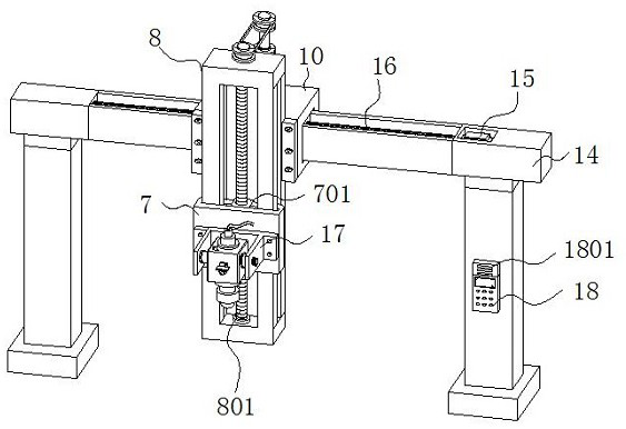
[0034] Both ends of the top of the frame body 2 are installed with support columns 11 , and the top between the support columns 11 is fixed with a mounting rail 14 . The transmission motor 15, the output end of the transmission motor 15 is connected with the second screw rod 16 through the rotating shaft, the middle position inside the mounting seat 10 is installed with the second screw rod sleeve 1001 matched with the second screw rod 16, and the mounting seat 10 The horizontal transmission design is formed by the second screw 16, the second screw sleeve 1001 and the mounting rail 14. The horizontal transmission design enables the glue injection head 21 to move and inject glue along the direction of the installation rail 14, and the glue injection is smoother and smoother. When the glue injection is completed, the glue injection head 21 is just above the recovery glue tank 12, so the residual silica gel inside the glue injection head 21 can drip to the recovery glue tank 12, which solves the problem that the residual glue on the glue injection head 21 drips on the working platform. It is difficult to clean up the problem, which ensures the cleanliness of the working platform.
[0035] A control panel 18 is installed at the middle position of one side of the support column 11 , and an alarm 1801 is arranged inside the control panel 18 , a mounting seat 10 is provided on the mounting rail 14 , and the side of the mounting seat 10 close to the frame body 2 is mounted with an alarm 1801 . Lifting mechanism 8, a first screw rod 801 is installed vertically at the middle position inside the lifting mechanism 8, and a first screw sleeve 701 matched with the first screw rod 801 is installed inside the moving seat 7, and the moving seat 7 is in the shape of a frame The design of the moving base 7 and the lifting mechanism 8 is a socket design. The design of the lifting mechanism 8 makes the height of the glue injection head 21 controllable, and it is convenient to extend the glue injection head 21 into the glue injection groove 2202 for glue injection. The glue is more precise, and the socket design makes the connection between the movable base 7 and the lifting mechanism 8 more stable, the movable base 7 is not easy to fall or shake left and right, and the glue injection effect is better.
[0036] The top end of the mounting seat 10 is fixed with the drive motor 9, and the output end of the drive motor 9 forms a transmission structure through the pulley mechanism 901 and the first screw rod 801. The transmission structure is designed so that the drive motor 9 can drive the first screw rod 801 to rotate, so that the The movable seat 7 provided with the first screw sleeve 701 ascends or descends, which is convenient for the smooth injection of glue, and the design is more reasonable.
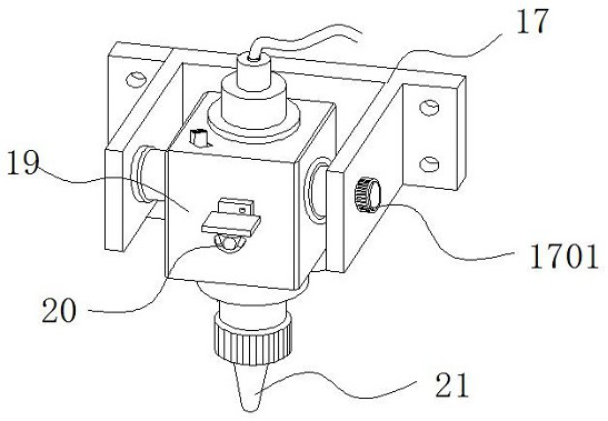
[0037] A movable seat 7 is installed on the side of the lifting mechanism 8 close to the frame body 2, and a hinge seat 17 is installed on the side of the movable seat 7 close to the frame body 2. The inside of the hinge seat 17 is hinged with a glue injection cylinder 19, and the glue injection cylinder 19 A tightening knob 1701 is installed at the hinge joint with the hinge base 17 , a laser displacement sensor 20 is installed at the middle position of the glue injection cylinder 19 near the frame body 2 , and a glue injection head 21 is installed at the bottom end of the glue injection cylinder 19 .
[0038] In summary, the automatic assembly equipment for LED light strips with groove glue injection height detection, when in use, turn on the power supply, first the electromagnetic slide rail 201 works, and drives the vacuum suction cup 5 to move to the placement box where the U-shaped half-sleeve 22 is placed Above 6, the hydraulic telescopic rod 4 is extended, which drives the vacuum suction cup 5 to move down, the vacuum pump 3 works, the vacuum suction cup 5 sucks the U-shaped half sleeve 22, and the hydraulic telescopic rod 4 and the electromagnetic slide rail 201 cooperate to move the U-shaped half sleeve. The tube 22 is placed in the limit slot 2401 of the limit plate 24, and then the servo motor 26 works to drive the third screw 25 to rotate, so that the movable seat 27 moves toward the support column 11, and the U-shaped half sleeve 22 is transferred to the laser Below the displacement sensor 20 , the laser displacement sensor 20 can detect the depth of the glue injection groove 2202 of the U-shaped half sleeve 22 , and the laser displacement sensor 20 transmits the detection information to the control panel 18 . If the depth of a section is shallow or deep, the control panel 18 can control the alarm 1801 to issue an alarm to remind the staff to remove the defective U-shaped half-sleeve 22, and then the servo motor 26 is reversed to drive the third screw 25 to rotate in the reverse direction. , the movable seat 27 returns to the bottom of the vacuum suction cup 5 again, and the vacuum suction cup 5 repeats the above operation to suck and clip the light strip under the limit bar 2201 of the U-shaped semi-sleeve 22, and complete the connection between the light strip and the U-shaped semi-sleeve 22. After assembly, the movable seat 27 is moved to the bottom of the glue injection head 21, the driving motor 9 works, and the first screw 801 is driven to rotate, so that the movable seat 7 is lowered, that is, the glue injection head 21 descends to the glue injection groove 2202, and then glue is injected The barrel 19 can seal the U-shaped half-sleeve 22. The input end of the glue injection barrel 19 is connected to the output end of the glue storage tank through a hose. During packaging, the mounting seat 10 can move left and right on the mounting rail 14. The groove 2202 is uniformly injected with glue, and the two ends of the glue injection groove 2202 are designed with openings, so the excess glue can overflow the U-shaped half sleeve 22 and fall into the recovery glue tank 12, and flow back to the glue storage under the action of the recovery pump 23 Recycling in the tank avoids the waste of glue.
[0039] The above description is only a preferred embodiment of the present invention, but the protection scope of the present invention is not limited to this. The equivalent replacement or change of the inventive concept thereof shall be included within the protection scope of the present invention.