
A Machine Tool Fixture Structure with Adjustable Feeding Speed

A machine tool fixture and adjustable technology, applied in the direction of clamping, manufacturing tools, metal processing machinery parts, etc., can solve the problem that the feeding speed cannot be adjusted, and achieve the effect of changing the operating speed

Active Publication Date: 2022-04-05
平湖市成功机械有限公司
View PDF0 Cites 0 Cited by
  • Summary
  • Abstract
  • Description
  • Claims
  • Application Information

AI Technical Summary

Problems solved by technology

[0005] Aiming at the deficiencies of the prior art, the present invention provides a machine tool fixture structure that can adjust the feeding speed, which has the advantage of adjusting the feeding speed and solves the problem that the feeding speed cannot be adjusted

Method used


Image

  • A Machine Tool Fixture Structure with Adjustable Feeding Speed
  • A Machine Tool Fixture Structure with Adjustable Feeding Speed
  • A Machine Tool Fixture Structure with Adjustable Feeding Speed

Examples


Embodiment Construction

[0025] The following will clearly and completely describe the technical solutions in the embodiments of the present invention with reference to the accompanying drawings in the embodiments of the present invention. Obviously, the described embodiments are only some, not all, embodiments of the present invention. Based on the embodiments of the present invention, all other embodiments obtained by persons of ordinary skill in the art without making creative efforts belong to the protection scope of the present invention.

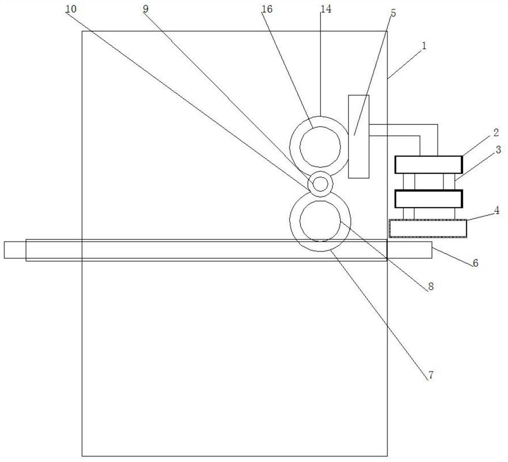
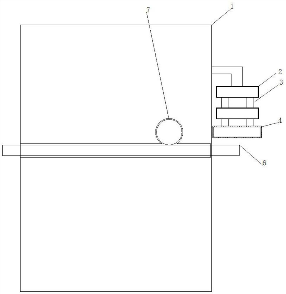
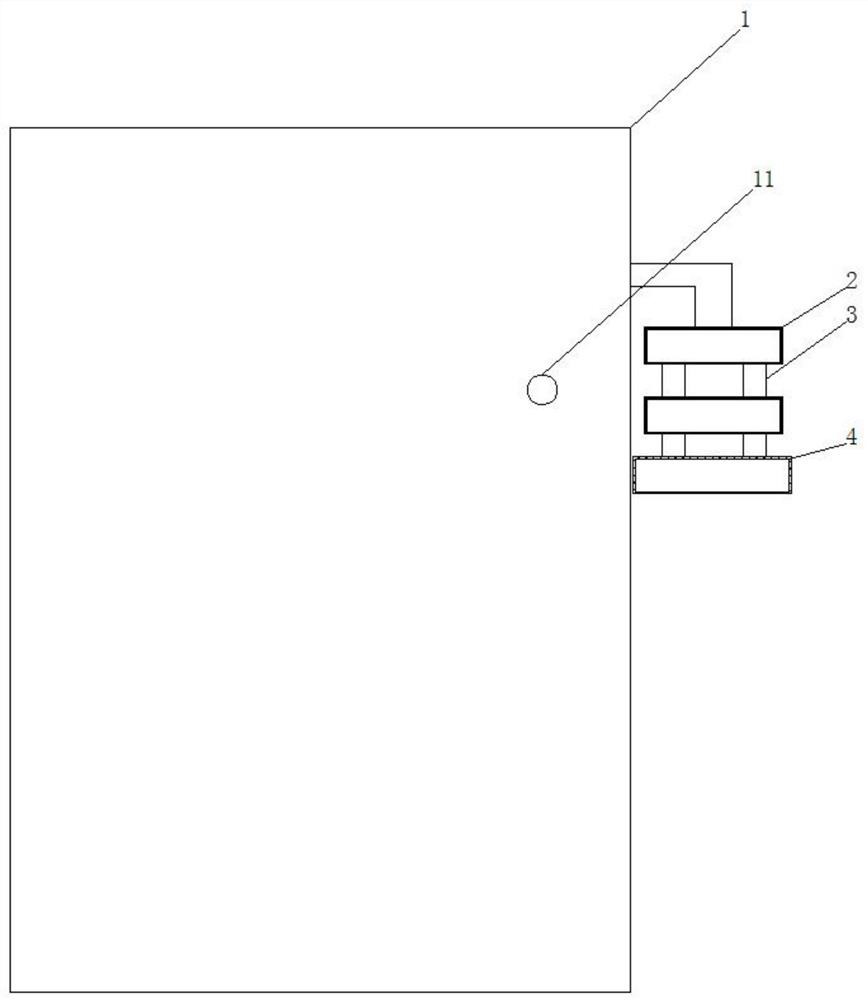
[0026] see Figure 1-6 , a machine tool fixture structure that can adjust the feeding speed, including a housing 1, the right side of the housing 1 is movably connected with a clamp body 2, the inner side of the clamp body 2 is movably connected with a fixed shaft 3, and the bottom of the fixed shaft 3 is fixedly connected There is a fixed seat 4, the top of the clip body 2 is fixedly connected with a gear bar 5, the inside of the housing 1 is provided with a ...


PUM


Abstract

The invention relates to the technical field of machine tool processing, and discloses a machine tool fixture structure that can adjust the feeding speed, including a shell, the right side of the shell is movably connected with a clamp body, and the top of the clamp body is fixedly connected with a gear The inside of the housing is provided with a feeding track, the top of the feeding track is provided with a pulley, the back side of the pulley is keyed to a power column, and the top of the power column is provided with a rotating shaft, and the rotating shaft The outer side of the rotating shaft is movably connected with a running wheel, the right side of the rotating shaft is provided with a transmission shaft, the outside of the transmission shaft is movably connected with a bracket, the back side of the transmission shaft is fixedly connected with a handle, and the upper side of the rotating wheel engages There is a transmission column, the back side key of the transmission column is connected with a motor, and the front key of the transmission column is connected with a gear. By turning the handle to change the position of the bracket, the bracket drives the runner to move left and right, and by adjusting the position of the runner on the power column and transmission column on the upper and lower sides, the effect of changing the running speed of the feeding track is achieved.

Description

technical field [0001] The invention relates to the technical field of machine tool processing, in particular to a machine tool fixture structure with adjustable feeding speed. Background technique [0002] Machine tool fixtures are an indispensable part of machine tool equipment. They play a great role in improving the quality and efficiency of machining. There are many types of machine tool fixtures, but their functions are basically to fix the workpiece and ensure machining accuracy. [0003] When the machine tool processes different workpieces, the time consumed is not the same, and most machine tool fixtures do not have the function of adjusting the feeding speed according to the different workpieces, which will lead to the occurrence of workpiece retention, which is not conducive to the processing and manufacturing of the machine tool , Contents of the invention [0004] (1) Solved technical problems [0005] Aiming at the deficiencies of the prior art, the inventi...

Claims


Application Information

Patent Timeline
Patent Type & Authority Patents(China)
IPC IPC(8): B23Q3/06B23Q7/00B23Q7/16
CPCB23Q3/06B23Q7/00B23Q7/16
Inventor 秦景平
Owner 平湖市成功机械有限公司
Learn More