Wall holing waste liquid collection device and construction method

A waste liquid collection and wall technology, which is applied in construction, building structure, construction material processing and other directions, can solve problems such as pollution, and achieve the effect of solving pollution problems.

Inactive Publication Date: 2020-11-24
CHINA MCC17 GRP
View PDF5 Cites 0 Cited by
  • Summary
  • Abstract
  • Description
  • Claims
  • Application Information

AI Technical Summary

Problems solved by technology

[0003] The purpose of the present invention is to solve the deficiencies in the prior art, so it proposes a waste liquid collection device and construction method for opening holes on the wall, which is beneficial to solve the problem that the waste liquid generated by the opening construction pollutes the wall surface, and saves manual cleaning cost

Method used


Image

  • Wall holing waste liquid collection device and construction method

Examples


Embodiment 1

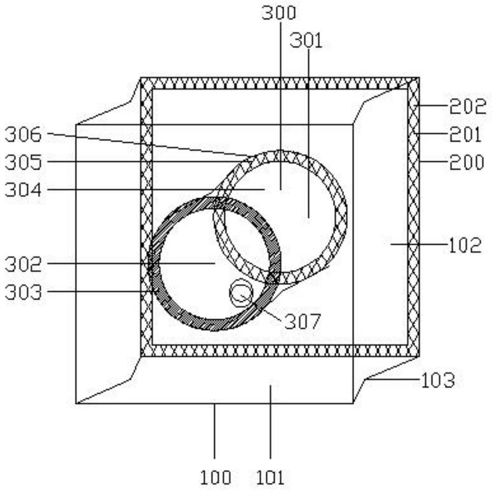
[0028] A waste liquid collection device for opening holes in the wall, including a container 100, a connector 200 and a diverter 300, the connector 200 is arranged on the back of the container 100, and is used to connect with the wall to be opened, and the diverter 300 runs through it horizontally The center of the container 100 is used as a channel for the drilling stroke of the rhinestone drill bit;

[0029] The container 100 includes a front panel 101, a back panel 102 and a side panel 103. The front panel 101 and the back panel 102 are parallel to each other and have the same size. The front panel 101 and the back panel 102 pass through a total of four sides: up, down, left and right. The panels 103 are connected, the front panel 101 and the back panel 102 are provided with openings, the two openings are equal in size, the front panel 101, the back panel 102 and the side panels 103 are combined into a closed box-shaped structure for collecting waste liquid from the opening;...

Embodiment 2

[0039] A construction method for a waste liquid collection device with holes in the wall, comprising the following steps:

[0040] Step 1: Stake out the position of the hole. Measure the position and size of the hole to be opened on the wall;

[0041]Step 2: Device installation, first align the center of the rear port 304 of the device with the center of the hole to be opened, tear off the film 2 306 and fix the rear port 304, then tear off the film 1 202, and place the rear port The back panel 102 of 304 circles is pasted on the wall, and finally the whole device is fixed on the wall;

[0042] Step 3: The rhinestone is installed in place, and the drill bit is passed through the folded front port 302, cavity 301, and rear port 304 in turn, and then aligned with the center of the planned hole on the wall;

[0043] Step 4: Device adjustment, stretching the side panel 103 and cavity 301 of the device outward along the axis of the rhinestone drill bit to open;

[0044] Step 5: D...


PUM


Abstract

The invention discloses a wall holing waste liquid collection device and a construction method, and relates to the building decoration engineering. The device is provided with a container, a connecting part and a dredging device, side faceplates, a front faceplate and a back faceplate in the container are utilized to constitute a box type structure which is used for collecting holing waste liquid,meanwhile, an adhesive strip on the connecting part is utilized to be connected with a to-be-holed wall, a covering film I is utilized to perform anti-pollution protection on the device before mounting, a cavity channel, a front port, a reinforcing ring, a bonding ring, a covering film II and a slurry discharge hole are formed in the dredging device, by means of the reinforcing ring, the front port and the front end of the cavity channel are in sealing connection with the front faceplate wholly after being mounted, a rear port is fixedly connected with the back faceplate through the bonding ring and fixed with the to-be-holed wall through the bonding ring, overall connectivity of the device is ensured, meanwhile, the rear end of the cavity channel is sealed, the adhesive strip of the backfaceplate is also a layer of sealing structure, both connecting effect and sealing effect can be realized, by means of the slurry discharge hole, the waste liquid in the cavity channel is dredged toenter a collector for unified treatment, and therefore, the pollution problem of the waste liquid is effectively solved.

Description

technical field [0001] The invention relates to the technical field of building decoration engineering, in particular to a device for collecting waste liquid from openings in walls and a construction method. Background technique [0002] During the construction of building installation and home decoration projects, due to the inaccurate position of the pre-buried openings or omissions and unburied during the construction of the building structure, it is often necessary to use rhinestones on the wall according to the positions of the air-conditioning openings, water, electricity and gas pipelines to be installed. Re-drilling, the waste liquid produced when the water drill is opening the hole is easy to pollute the wall surface. There is no specific equipment to collect it in the prior art, and an effective method needs to be used to collect the waste liquid. Contents of the invention [0003] The purpose of the present invention is to solve the deficiencies in the prior art...

Claims


Application Information

Patent Timeline
Patent Type & Authority Applications(China)
IPC IPC(8): E04G21/00E04G21/30
CPCE04G21/00E04G21/30
Inventor 乔小明孔繁锋吕正东
Owner CHINA MCC17 GRP
Why Eureka
Try Eureka