Joint spacer
A joint spacer, joint technology, applied in the field of knee spacers and hip spacers, which can solve the problems of limitation, implant fracture, and unknown results.
- Summary
- Abstract
- Description
- Claims
- Application Information
AI Technical Summary
Problems solved by technology
Method used
Image
Examples
Embodiment Construction
[0168] Figure 22 The characteristic range of tensile stress-strain curves for preferred materials is shown. It specifically shows the 50% tensile stress value of the material in the Shore A hardness range of 20-77, which should be greater than 3.8N / mm 2 , preferably greater than 4.6N / mm 2 , in a more ideal situation, preferably greater than 6N / mm 2 . Should Figure 22 Also shows a stress curve with a yield characteristic which should be avoided unless the yield point is above 10N / mm 2super high value. The "S-curve" ("S-process") indicates that a suitable material with sufficient 50% tensile stress may have lower elastic modulus and tensile stress value.
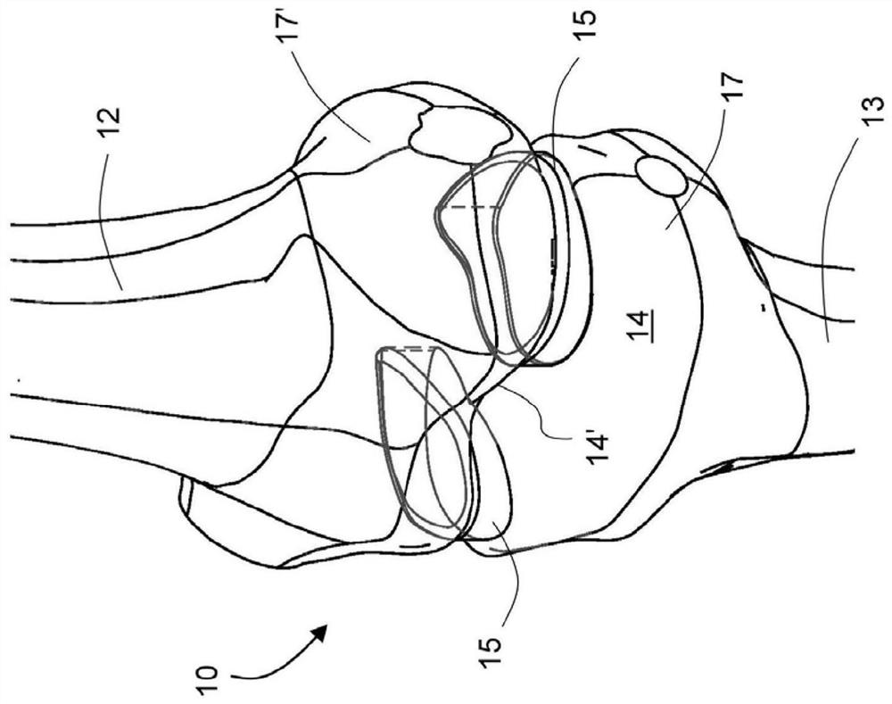
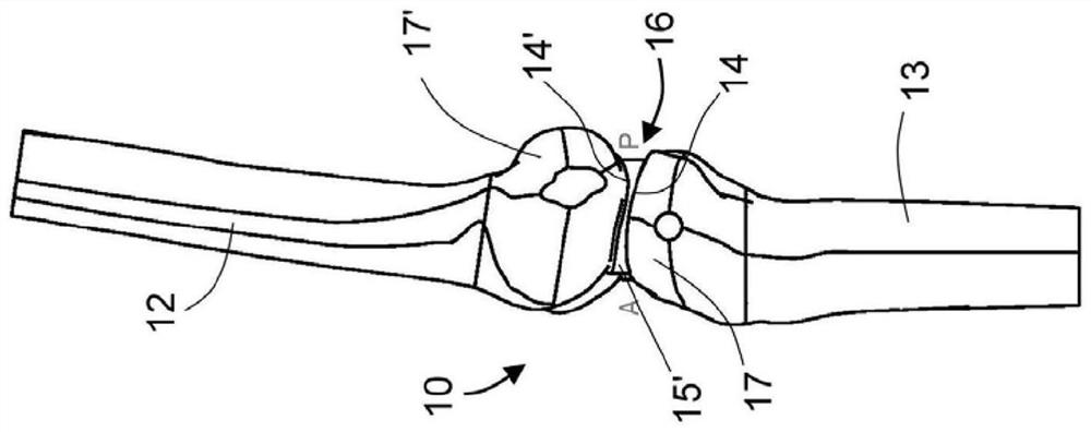
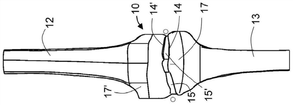
[0169] Figure 1a -c shows different views of the knee joint 10, and various parts of the femur 12 (femur) and the lower leg 13 (tibia). Between the articular surfaces 14 and 14', meniscus spacers 15 and 15' are placed to replace worn and damaged (naturally damaged) menisci. In order to protect the material of the m...
PUM
| Property | Measurement | Unit |
|---|---|---|
| compression ratio | aaaaa | aaaaa |
| elongation | aaaaa | aaaaa |
| thickness | aaaaa | aaaaa |
Abstract
Description
Claims
Application Information
 - R&D
- Intellectual Property
- Life Sciences
- Materials
- Tech Scout
- Unparalleled Data Quality
- Higher Quality Content
- 60% Fewer Hallucinations
Browse by: Latest US Patents, China's latest patents, Technical Efficacy Thesaurus, Application Domain, Technology Topic, Popular Technical Reports.
© 2025 PatSnap. All rights reserved.Legal|Privacy policy|Modern Slavery Act Transparency Statement|Sitemap|About US| Contact US: help@patsnap.com


