
Rolling device for welding machining of cylindrical reinforcement cage

A rolling device and steel cage technology, applied in auxiliary devices, wire processing, welding equipment, etc., can solve problems such as time-consuming and labor-intensive, low efficiency of steel cage production, and inability to meet the needs of engineering construction, so as to improve welding efficiency and high degree of automation Effect

Active Publication Date: 2020-11-27
广东华亮建设有限公司
View PDF16 Cites 1 Cited by
  • Summary
  • Abstract
  • Description
  • Claims
  • Application Information

AI Technical Summary

Problems solved by technology

[0003] In the existing welding process of cylindrical steel cages, it is necessary to manually turn over the steel cages to be welded, and transfer each welding point to the welding station in turn, which is time-consuming and laborious. Larger engineering construction needs

Method used


Image

  • Rolling device for welding machining of cylindrical reinforcement cage
  • Rolling device for welding machining of cylindrical reinforcement cage
  • Rolling device for welding machining of cylindrical reinforcement cage

Examples


Embodiment Construction

[0041] In order for those skilled in the art to better understand the technical solution of the present invention, the present invention will be further described below in conjunction with the examples and accompanying drawings, but the embodiments of the present invention are not limited thereto.

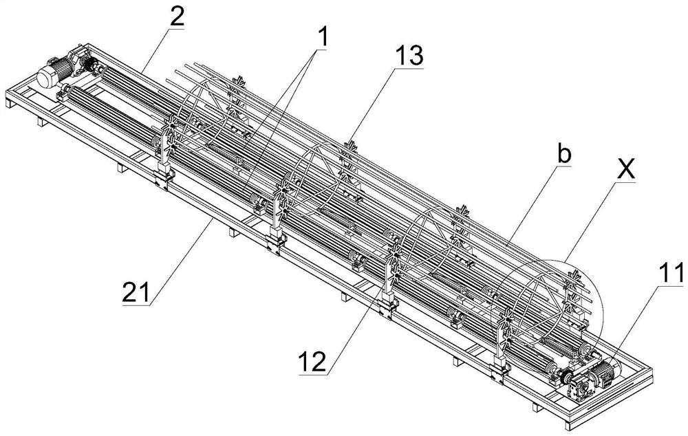
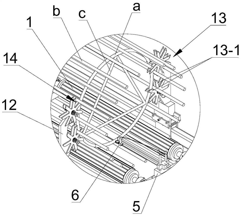
[0042] see Figure 1-2 and Figure 7-8 , the rolling device that is used for the welding processing of cylindrical reinforcement cage in the present embodiment, comprises the roller driving mechanism that is used to drive reinforcement cage to roll and is used to measure the rolling velocity measuring mechanism of the rotating speed of reinforcement cage and the rolling support mechanism, described roller The drive mechanism includes two sets of rollers 1 arranged in parallel and a rotary drive mechanism for driving the two sets of rollers 1 to rotate. The two sets of rollers 1 are rotatably arranged on the frame 2 . Two sets of rolling support mechanisms are provided, and the two...


PUM


Abstract

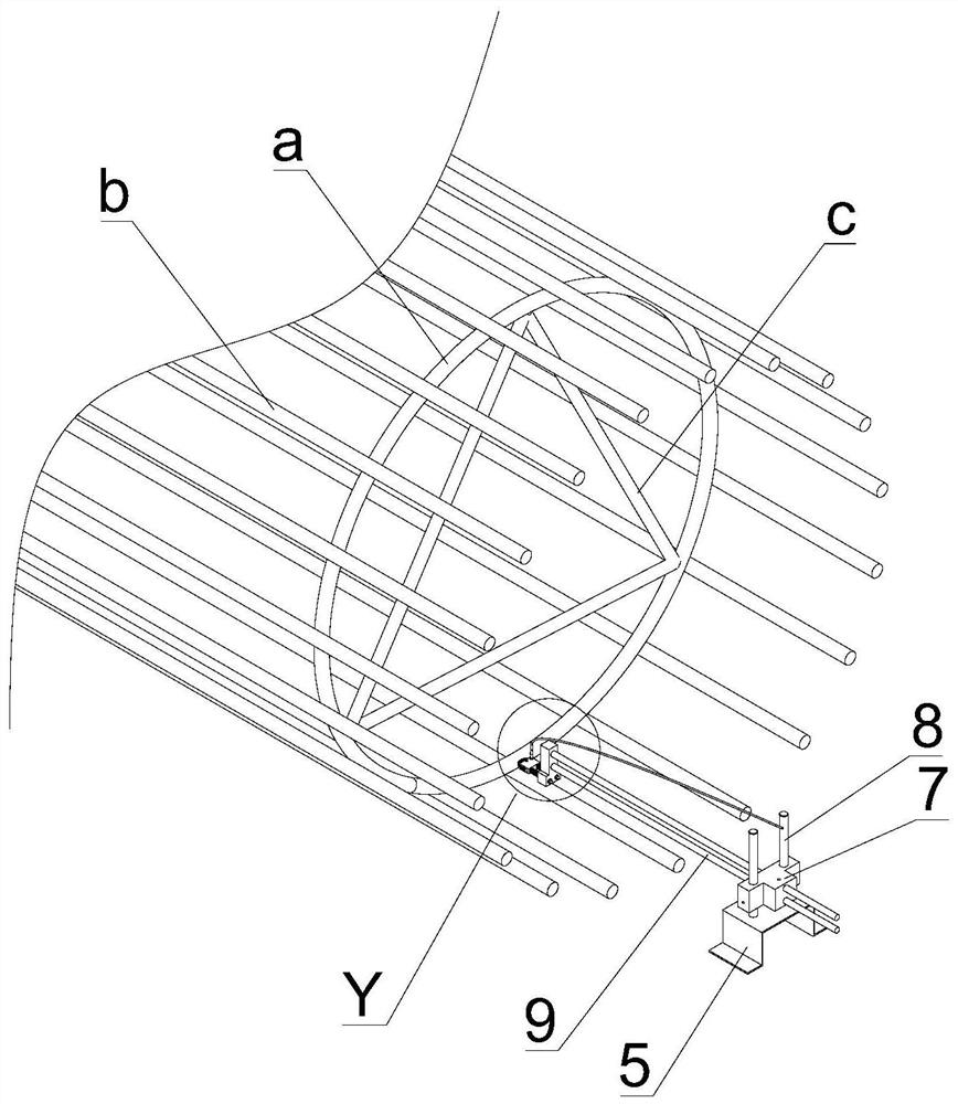
The invention discloses a rolling device for welding machining of a cylindrical reinforcement cage. The rolling device comprises a roller driving mechanism and a rolling speed measuring mechanism. Theroller driving mechanism comprises two sets of rollers and a rotating driving mechanism. The rolling speed measuring mechanism comprises a speed measuring mounting frame, a speed measuring wheel anda photoelectric element. The speed measuring mounting frame is arranged at an end of a rack and provided with a measuring mounting groove. The speed measuring wheel is rotationally connected to the interior of the measuring mounting groove of the speed measuring mounting frame. The rotating center of the speed measuring wheel is perpendicular to the axis of a stirrup ring of the reinforcement cage. The speed measuring wheel is provided with a plurality of light transmitting holes in the circumferential direction. The photoelectric element comprises a light emitting source and a light sensitiveelement. The light emitting source and the light sensitive element are arranged on two sides of the speed measuring wheel correspondingly and face the rotating paths of the light transmitting holes of the speed measuring wheel. The rolling device can automatically and accurately drive the reinforcement cage to turn over, all welding points are sequentially transferred into a welding station, theautomation degree is high, and the welding efficiency can be improved easily.

Description

technical field [0001] The invention relates to steel cage welding equipment, in particular to a rolling device used for cylindrical steel cage welding. Background technique [0002] The reinforcement cage is the foundation skeleton of the pile, which is mainly composed of metal components such as the main reinforcement, stirrups, and winding reinforcements. It is commonly used in steel-concrete structures of modern buildings. Among them, during the construction process, the pile holes are first drilled down on the predetermined ground, and then the steel cages are put into the pile holes, and then filled or poured with concrete. After a certain period of maintenance, the design bearing pressure can be reached. , in order to ensure the construction requirements of its superstructure and future use requirements. [0003] In the existing welding process of cylindrical steel cages, it is necessary to manually turn over the steel cages to be welded, and transfer each welding po...

Claims


Application Information

Patent Timeline
Patent Type & Authority Applications(China)
IPC IPC(8): B23K37/053B23K37/047B21F27/20
CPCB23K37/0533B23K37/047B21F27/20
Inventor 罗伟权
Owner 广东华亮建设有限公司
Learn More