Bearing hole processing device

A processing device and bearing hole technology, applied in the field of mechanical processing, can solve the problems affecting the processing accuracy and processing efficiency, applicability and practical limitations, easy to shift or loosen, etc., so as to facilitate the fixing of equipment and realize automation Operation and reduction of cutting force

Inactive Publication Date: 2020-11-27
马鞍山骋运博精密机械有限责任公司
View PDF0 Cites 0 Cited by
  • Summary
  • Abstract
  • Description
  • Claims
  • Application Information

AI Technical Summary

Problems solved by technology

[0002] Bearing is an important part of contemporary mechanical equipment. Its main function is to support the mechanical rotating body, reduce the friction coefficient during its movement, and ensure its rotation accuracy. A pin hole is machined near the bearing hole. In order to ensure that the machined hole The accuracy of the position generally needs to fix the bearing body. The traditional technology mainly uses manual compression of the bearing body and then carries out the hole position processing operation. It is easy to shift or loose during processing, which affects the processing accuracy and processing efficiency. Efficiency, but there are also certain security risks, so the applicability and practicality are limited

Method used


Image

  • Bearing hole processing device
  • Bearing hole processing device

Examples


Embodiment

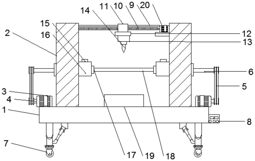
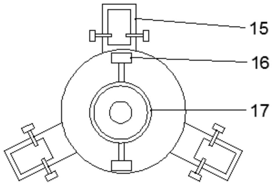
[0018] Example: such as Figure 1-2 As shown, a bearing hole processing device of the present invention includes a workbench 1, a drill bit 14 and a three-jaw chuck 15. The top of the workbench 1 is provided with two columns 2, and the columns 2 are respectively arranged on both sides of the workbench 1. The sides of the two columns 2 close to the workbench 1 are provided with a drive motor 3, the drive motor 3 is fixedly connected to the workbench 1, the drive motor 3 is fixedly connected to the drive shaft 4, and the top of the drive shaft 4 is provided with a pulley 5. The transmission shaft 4 is fixedly connected with the pulley 5, the top of the transmission shaft 4 is provided with a chuck shaft 6, one end of the chuck shaft 6 is rotationally connected with the column 2 through a bearing, the other end of the chuck shaft 6 is provided with a pulley 5, and the drive motor 3 It is rotationally connected with the chuck shaft 6 through the pulley 5, the chuck shaft 6 is loca...


PUM


Abstract

The invention provides a bearing hole processing device. The bearing hole processing device comprises a workbench, a drill bit and three-jaw chucks. Two stand columns are arranged at the top end of the workbench and arranged on the two sides of the workbench correspondingly. Driving motors are arranged on the sides, close to the workbench, of the two stand columns and fixedly connected with the workbench. A transmission shaft is fixedly connected with one side of each driving motor, a belt pulley is arranged at the top end of each transmission shaft, and the transmission shafts and the belt pulleys are fixedly connected. A chuck rotating shaft is arranged at the top end of each transmission shaft, one end of each chuck rotating shaft is connected with the corresponding stand column in a rotating mode through a bearing, and a belt pulley is arranged at the other end of each chuck rotating shaft. The driving motors and the chuck rotating shaft are connected in a rotating mode through thebelt pulleys, and the chuck rotating shafts are located on the tops of the driving motors. A ball screw is fixedly connected with one side of a second driving motor, a guide rod is arranged on the top of the ball screw, and a sliding block is connected with the surface of the ball screw in a sliding mode. A telescopic column is fixedly connected with the bottom end of the sliding block, a connecting column is fixedly connected with the bottom end of the telescopic column, and the drill bit is detachably connected with the bottom of the connecting column.

Description

technical field [0001] The invention relates to the field of mechanical processing, in particular to a bearing hole processing device. Background technique [0002] Bearing is an important part of contemporary mechanical equipment. Its main function is to support the mechanical rotating body, reduce the friction coefficient during its movement, and ensure its rotation accuracy. A pin hole is machined near the bearing hole. In order to ensure that the machined hole The accuracy of the position generally needs to fix the bearing body. The traditional technology mainly uses manual compression of the bearing body and then carries out the hole position processing operation. It is easy to shift or loose during processing, which affects the processing accuracy and processing efficiency. Efficiency, but also there are certain security risks, so the applicability and practicality are limited. The competition of modern manufacturing technology is actually the competition of manufactu...

Claims


Application Information

Patent Timeline
Patent Type & Authority Applications(China)
IPC IPC(8): B23Q3/06B23Q5/28B23Q5/40B23Q11/00
CPCB23Q3/06B23Q5/28B23Q5/40B23Q11/00B23Q11/0042
Inventor 杨小妹刘龙云马梦醒俞雷李波
Owner 马鞍山骋运博精密机械有限责任公司
Why Eureka
Try Eureka