A device for glazing ceramic cups

A technology for ceramic cups and equipment, which is applied to ceramic molding machines, manufacturing tools, etc., can solve the problems of poor control of the height of ceramic cups and slow glazing speed, and achieve the effect of fast glazing and fast glazing.

Active Publication Date: 2022-07-22
潮州市精美工艺品有限公司
View PDF8 Cites 0 Cited by
  • Summary
  • Abstract
  • Description
  • Claims
  • Application Information

AI Technical Summary

Problems solved by technology

[0005] In order to overcome the disadvantages that the speed of glazing with a hand-held cup is relatively slow, and it is difficult to control the height of the ceramic cup in the glaze slurry during the glazing process, so that the glaze slurry enters the interior of the ceramic cup, the technical problem of the present invention is: to provide A device for glazing ceramic cups with fast glazing speed and no glaze slurry entering the interior of the ceramic cup

Method used


Image

  • A device for glazing ceramic cups
  • A device for glazing ceramic cups
  • A device for glazing ceramic cups

Examples


Embodiment 1

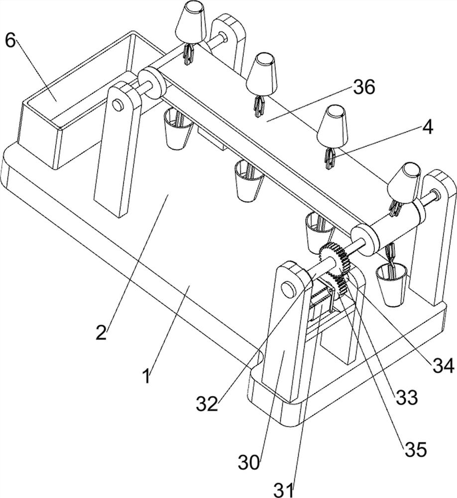
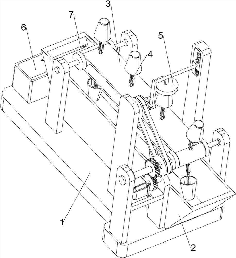
[0022] A device for glazing ceramic cups, such as figure 1 As shown, it includes a bottom plate 1, a charging chute 2, a conveying mechanism 3, a clamping mechanism 4 and a pressing mechanism 5. A charging chute 2 is provided on the rear side of the upper portion of the bottom plate 1, and a conveying mechanism 3 is provided on the upper portion of the bottom plate 1. 2 is located below the conveying mechanism 3, the conveying mechanism 3 is provided with a plurality of clamping mechanisms 4 evenly spaced, and the middle of the upper part of the bottom plate 1 is provided with a pressing mechanism 5.

[0023] When the user needs to glaze the ceramic cup, the device can be used. First, the user can pour the glaze slurry into the charging tank 2, and then place the ceramic cup to be glazed on the clamping mechanism. 4, and then move the ceramic cup to be glazed into the charging tank 2 through the transmission mechanism 3, so that the ceramic cup can be glazed. After the glazing...

Embodiment 2

[0025] On the basis of Example 1, as Figure 1-5 As shown, the transmission mechanism 3 includes a first bearing seat 30, a servo motor 31, a first rotating shaft 32, a full gear 33, a second rotating shaft 34, a missing gear 35, a conveyor belt 36 and a second bearing seat 37. Bearing seats are arranged symmetrically on both sides, and a first rotating shaft 32 is rotatably arranged between the two bearing seats on the left and right sides. The front side of the first rotating shaft 32 on the right is provided with a full gear 33, A conveyor belt 36 is connected between a rotating shaft 32. A second bearing seat 37 is provided on the right front side of the upper part of the bottom plate 1. The second bearing seat 37 is located at the rear side of the first bearing seat 30 on the right front side. The upper part of the second bearing seat 37 is provided with a servo The motor 31 and the second bearing seat 37 are rotatably provided with a second rotating shaft 34, the second ...

Embodiment 3

[0032] On the basis of Example 2, as figure 1 As shown, it also includes a storage tank 6, a storage tank 6 is installed on the left side of the upper part of the bottom plate 1, and a control dye capacity tank 7 is opened on the left side of the charging tank 2.

[0033] The user can pour the glaze slurry into the charging tank 2. In order to prevent the glaze slurry from flowing into the ceramic cup during the glazing process of the ceramic cup, when the glaze slurry in the charging tank 2 is too much, the glaze slurry will be controlled by the dye capacity. The tank 7 flows into the storage tank 6. When the glaze slurry in the storage tank 6 reaches a certain amount, the glaze slurry in the storage tank 6 can be poured back into the charging tank 2, so that the glaze slurry can be reused.


PUM


Abstract

The invention relates to a glazing device, in particular to a device for glazing a ceramic cup. The technical problem of the present invention is to provide a device for glazing a ceramic cup with a fast glazing speed and without the glaze slurry entering the interior of the ceramic cup. A device for glazing a ceramic cup, comprising: a bottom plate, the bottom plate is used to install the whole device; a charging chute, the charging chute is arranged on one side of the upper part of the bottom plate; a conveying mechanism, the conveying mechanism It is arranged on one side of the upper part of the bottom plate, and the charging chute is located under the conveying mechanism; a clamping mechanism, the clamping mechanism is arranged on the conveying mechanism; a pressing mechanism, the pressing mechanism is arranged on the conveying mechanism The upper middle of the bottom plate. The invention achieves the effect that the glazing speed is fast, and the glaze slurry does not enter the interior of the ceramic cup; by placing the ceramic cup on the cross bar, the conveyor belt sequentially moves the ceramic cup into the charging trough for glazing, so that the glazing can be realized. Quick glaze.

Description

technical field [0001] The invention relates to a glazing device, in particular to a device for glazing a ceramic cup. Background technique [0002] There are many kinds of glazes, substances made of quartz, feldspar, borax, clay, etc. as raw materials, which are used to coat the surface of porcelain and pottery. After the glaze slurry is adjusted, the glaze slurry is applied on the surface of the ceramic. This process is called glazing. It can be divided into crystalline glaze and cracked glaze after firing into a vitreous luster. A vitreous glaze layer is coated on the fired blank, mainly for protection and decoration. [0003] At present, people mostly use manual methods to glaze ceramic cups. People first pour the glaze slurry into a suitable container, and then hold the upper mouth of the ceramic cup and sink the cup into the glaze slurry to glaze the cup. , The method of manually holding the ceramic cup for glazing has the disadvantage that the glazing speed is slow,...

Claims


Application Information

Patent Timeline
Patent Type & Authority Patents(China)
IPC IPC(8): B28B11/04
CPCB28B11/044
Inventor 李传杰
Owner 潮州市精美工艺品有限公司
Why Eureka
Try Eureka