
Electric propulsion device for ship

A technology for electric propulsion and ships, which is applied in the direction of ship propulsion, propulsion transmission devices, propulsion device engines, etc., can solve the problems of low transmission efficiency, weak wind resistance, poor risk resistance, etc., and achieve fast navigation speed, convenient disassembly and reliable connection Effect

Inactive Publication Date: 2020-11-27
JIANGSU UNIV OF SCI & TECH +2
View PDF0 Cites 3 Cited by
  • Summary
  • Abstract
  • Description
  • Claims
  • Application Information

AI Technical Summary

Problems solved by technology

[0002] Ship electric propulsion refers to a propulsion method that uses electric motors to drive propellers to propel ships. The general ship electric propulsion device is a single propeller propulsion structure. This structure has low transmission efficiency and weak wind resistance. Once the propeller is damaged, the ship will not be able to Navigation, poor risk resistance
[0003] The structure of the existing ship electric propulsion device is relatively complicated, and the installation and disassembly of the propeller is inconvenient; in addition, the current ship electric propulsion device consumes a lot of power, the energy utilization rate is not high enough, and it lacks the corresponding emergency power supply, so it is difficult to deal with emergencies

Method used


Image

  • Electric propulsion device for ship
  • Electric propulsion device for ship
  • Electric propulsion device for ship

Examples


Embodiment 1

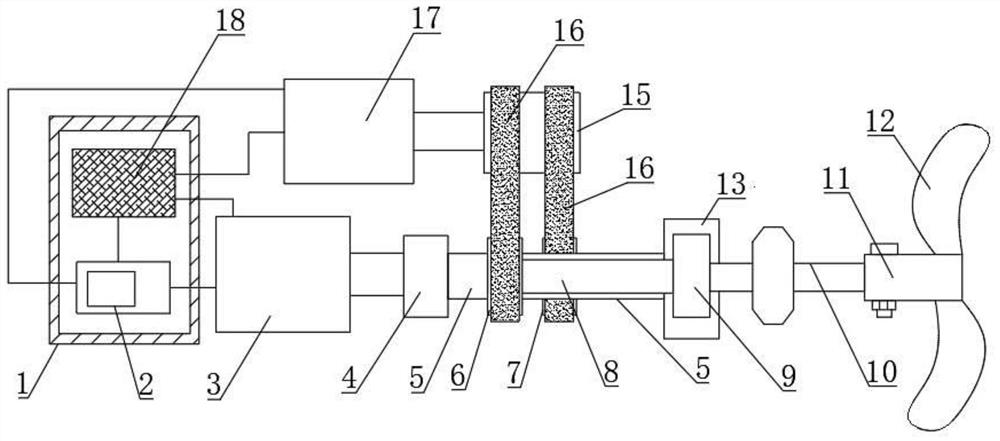
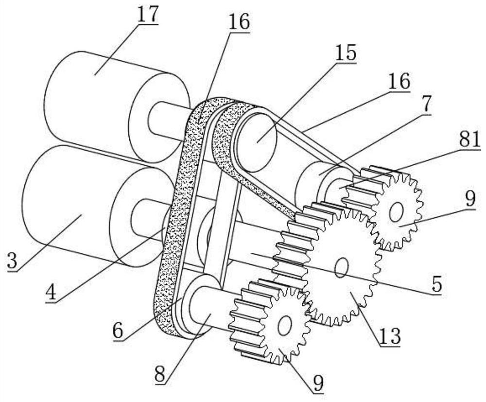
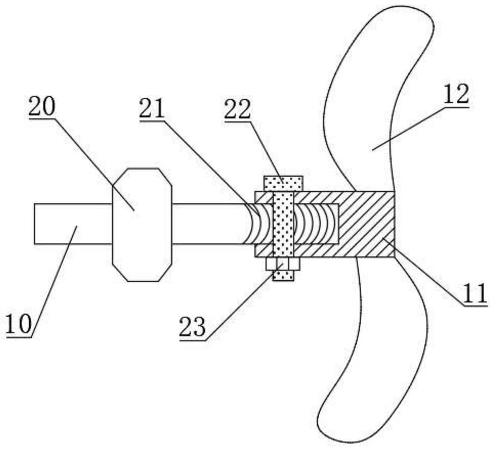
[0023] see figure 1 , figure 2 and image 3 , a ship electric propulsion device, comprising a drive motor 3, a reducer 4, a shaft 11, a bolt 22 and a generator 17, the output shaft of the drive motor 3 is connected to the input end of the reducer 4, and the output of the reducer 4 The end is fixedly connected with the first rotating shaft 5, and the right end of the first rotating shaft 5 is connected with a driving gear 13, and the front and rear of the driving gear 13 are respectively meshed with a driven gear 9, and the right end surface of each driven gear 9 is Connected with the second rotating shaft 10, the side of the second rotating shaft 10 is provided with thread 21, and the left end surface of the shaft 11 is provided with a threaded blind hole, the second rotating shaft 10 and the shaft 11 are connected by thread, and the bolt 22 penetrates at the same time The second rotating shaft 10 and the axle rod 11, the right end of the axle rod 11 is connected with the p...

Embodiment 2

[0028] see figure 1 , figure 2 and image 3 , this embodiment is a further description of the ship electric propulsion device described in Example 1. In this embodiment, the number of the driven gear 9, the second rotating shaft 10 and the shaft rod 11 is two And all about the symmetry plane of the first rotating shaft 5, symmetrically arranged front and back; The length of the third rotating shaft 8 is greater than the length of the fourth rotating shaft 81, and the structure and size of the driving pulley two 7 and the driving pulley one 6 All are the same, there is a gap between the belt 16 on the driving pulley two 7 and the belt 16 on the driving pulley one 6, which not only ensures the same speed of movement of the two belts 16, but also prevents the two belts 16 from interfering with each other The outer side of the second rotating shaft 10 is provided with a bearing seat 20, the bearing seat 20 is equipped with a bearing, the inner hole of the bearing is fixedly con...


PUM


Abstract

The invention discloses an electric propulsion device for a ship. The device comprises a driving motor and a generator, an output shaft of the driving motor is connected with the input end of a speedreducer; the output end of the speed reducer is fixedly connected with a first rotating shaft, the right end of the first rotating shaft is connected with a driving gear, the front portion and the rear portion of the driving gear are each connected with a driven gear in an engaged mode, the right end face of each driven gear is connected with a second rotating shaft, and the second rotating shaftsare in threaded connection with shaft rods; an output shaft of the generator is connected with a driven belt wheel, and a first driving belt wheel and a second driving belt wheel are both connected with the driven belt wheel through belts. The device comprises the two propellers, and is high in sailing speed and high in wind resistance; through the arrangement of the driving gear, the driven gears and the generator, a part of mechanical energy can be converted into electric energy, the electric energy is stored in a storage battery, and the stored electric energy serves as an emergency powersupply.

Description

technical field [0001] The invention relates to the technical field of ship electric propulsion, in particular to a ship electric propulsion device. Background technique [0002] Ship electric propulsion refers to a propulsion method that uses a motor to drive a propeller to propel a ship. The general ship electric propulsion device is a single propeller propulsion structure. This structure has low transmission efficiency and weak wind resistance. Once the propeller is damaged, the ship will not be able to Navigation, poor risk resistance. [0003] The structure of the existing ship electric propulsion device is relatively complicated, and the installation and disassembly of the propeller is not convenient; in addition, the current ship electric propulsion device consumes a lot of power, the energy utilization rate is not high enough, and it lacks the corresponding emergency power supply, so it is difficult to deal with emergencies. [0004] Therefore, there is a need to p...

Claims


Application Information

Patent Timeline
Patent Type & Authority Applications(China)
IPC IPC(8): B63H21/17B63H23/02
CPCB63H21/17B63H23/02B63H2023/0216
Inventor 苏贞栾蓉宇王荣徐刚刘昆刘永涛王施齐刘磊
Owner JIANGSU UNIV OF SCI & TECH
Learn More