New energy automobile maintenance platform

A new energy vehicle and maintenance platform technology, applied in the field of new energy vehicle maintenance platform, can solve the problems of insufficient safety guarantee of the device and lack of personal safety, and achieve the effects of improving firmness, reducing labor, and ensuring personal safety.

Inactive Publication Date: 2020-11-27
焦培刚
View PDF8 Cites 3 Cited by
  • Summary
  • Abstract
  • Description
  • Claims
  • Application Information

AI Technical Summary

Problems solved by technology

[0003] In order to solve such problems, hanger devices have appeared on the market, and the car is hoisted for maintenance. However, this type of device does not have sufficient safety protection. Personal safety, therefore, there is an urgent need to always use the car maintenance platform to solve such problems

Method used


Image

  • New energy automobile maintenance platform
  • New energy automobile maintenance platform
  • New energy automobile maintenance platform

Examples


Embodiment 1

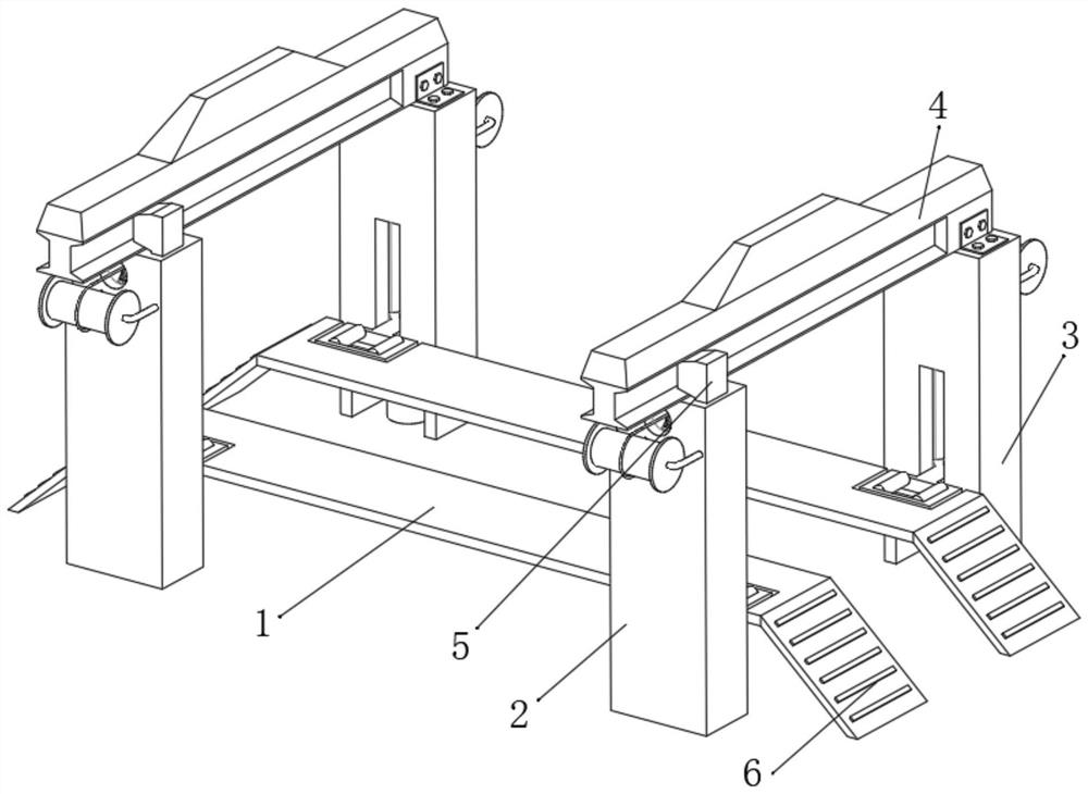
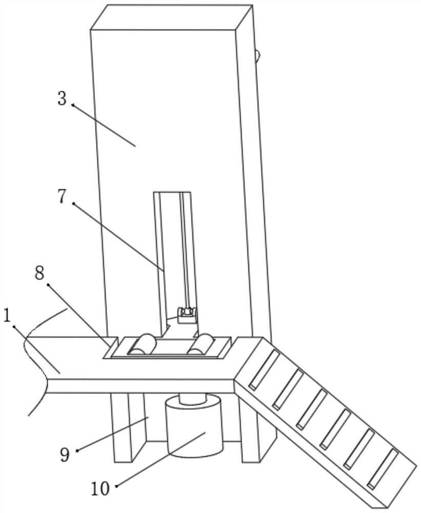
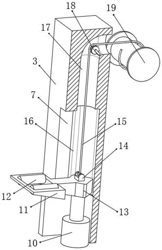
[0031] refer to Figure 1-4 , a new energy vehicle maintenance platform, including a fixed column 3, a beam 4, a sliding column 2 and a support plate 1, the fixed column 3 and the beam 4 are welded, the internal structure of the fixed column 3 and the sliding column 2 is the same as the external structure, The inside of the fixed column 3 is provided with a rope groove 17, an anti-sway groove 16 and a rectangular groove 7, and the rope groove 17 is located at the top of the fixed column 3, and the anti-sway groove 16 is located at the middle of the fixed column 3, and the rectangular groove 7 is located at the anti-sway groove On one side of 16, the inwall of anti-shake groove 16 is slidably connected with load-bearing block 13, and load-bearing block 13 is compatible with anti-shake groove 16, and one side outer wall of load-bearing block 13 is welded with load-bearing plate 11, and the top of load-bearing block 13 is welded There is a connecting block 14, and the inside of t...

Embodiment 2

[0035] refer to Figure 5 , a maintenance platform for new energy vehicles. Compared with Embodiment 1, the position of the outer wall of one side of the fixed column 3 close to the top is connected with an electric telescopic rod 22 by bolts, and one end of the electric telescopic rod 22 is connected to the sliding column 2 connected by bolts.

[0036] Working principle: when in use, move the car to be overhauled to the support plate 1, the inclined plates 6 located on both sides of the support plate 1 facilitate the car to drive to the support plate 1, the front and rear wheels of the car must be located on the load-bearing plate 11, according to For different models, the electric telescopic rod 22 can be used to adjust the distance between the fixed column 3 and the sliding column 2. When the car needs to be opened, the wire winder 19 and the hydraulic rod 10 are opened at the same time, and the load-bearing block 13 is slowly raised. The diamond-shaped design of the anti-...


PUM


Abstract

The invention discloses a new energy automobile maintenance platform. The new energy automobile maintenance platform comprises a fixing column, a cross beam, a sliding column and a supporting plate, wherein the fixing column and the cross beam are welded, the internal structure and the external structure of the fixing column and the internal structure and the external structure of the sliding column are the same, a rope groove, an anti-shaking groove and a rectangular groove are formed inside the fixing column, the rope groove is located in the top of the fixing column, the anti-shaking grooveis located in the middle of the fixing column, the rectangular groove is located in one side of the anti-shaking groove, the inner wall of the anti-shaking groove is slidably connected with a bearingblock, the bearing block matches with the anti-shaking groove, and the outer wall of one side of the bearing block is fixedly connected with a bearing plate. According to the new energy automobile maintenance platform, an automobile can be lifted and disengaged from the ground, multiple layers of protective measures are set, the design of the anti-shaking groove prevents the bearing plate from shaking, a steel wire rope matches with a hydraulic rod, the overall stability is guaranteed when the automobile is lifted, a space is reserved between the supporting plate and the ground, a worker hasa safe operation space, the personal safety is guaranteed, and the overall structure of the device is firm and stable.

Description

technical field [0001] The invention relates to the technical field of vehicle maintenance platforms, in particular to a new energy vehicle maintenance platform. Background technique [0002] For the overhaul of the car, part of it needs to be carried out at the bottom of the car to check the damage of the chassis, axles, etc. In the current repair shop, for the overhaul of the bottom of the car, it is generally to set up an overhaul slot on the ground, and place the car on the overhaul. Above the tank, repair workers then enter the maintenance tank, and carry out the maintenance of the bottom of the vehicle in the maintenance tank, and it is troublesome to clean up sewage and sundries in the maintenance tank. [0003] In order to solve such problems, hanger devices have appeared on the market, and the car is hoisted for maintenance. However, this type of device does not have sufficient safety protection. Personal safety, therefore, is urgently needed to solve such problems...

Claims


Application Information

Patent Timeline
IPC IPC(8): B66F7/02B66F7/20B66F7/28B60S5/00
CPCB60S5/00B66F7/02B66F7/20B66F7/28
Inventor 焦培刚侯钦中张伟李寅男刘阳窦裕盛
Owner 焦培刚
Why Eureka
Try Eureka