Industrial circulating cooling water descaling equipment
A technology for circulating cooling water and first descaling, applied in descaling and water softening, water/sludge/sewage treatment, chemical instruments and methods, etc., can solve the problem of increasing maintenance costs, reducing the service life of descaling components, reducing The descaling time and other issues can improve the descaling effect, reduce the maintenance cost and improve the service life.
- Summary
- Abstract
- Description
- Claims
- Application Information
AI Technical Summary
Problems solved by technology
Method used
Image

Examples
Embodiment 1
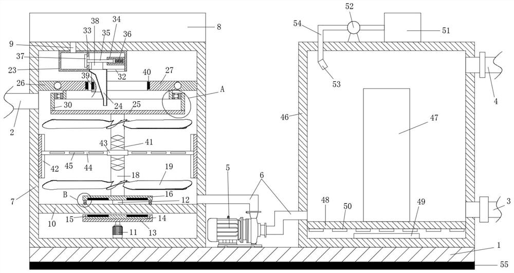
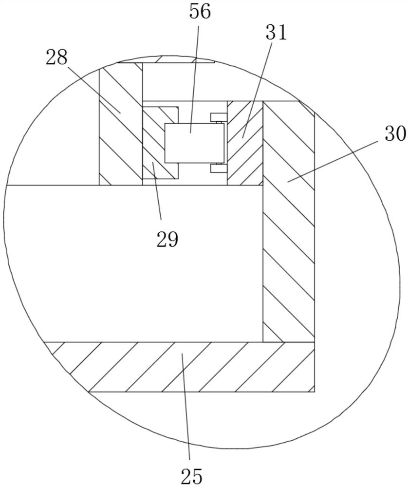
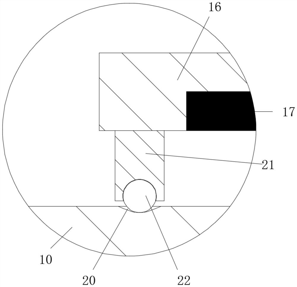
[0023] see Figure 1-4, a kind of descaling equipment for industrial circulating cooling water, comprising a water inlet pipe 2, a descaling pipe 3 with a valve, an outlet pipe 4, a base 1 and a physical descaling assembly, the physical descaling assembly is arranged on the base 1, the A chemical descaling component is arranged before the physical descaling component, a water pump 5 is arranged between the chemical descaling component and the physical descaling component, and a water pump 5 is arranged between the chemical descaling component and the water pump 5 and between the water pump 5 and the physical descaling component. The chemical descaling assembly includes the first descaling box 7 fixedly installed on the base 1, the storage tank 8 containing the antiscalant and the stirring assembly for mixing the antiscalant , the storage box 8 is fixedly installed on the top of the first descaling box 7, and the storage box 8 is fixedly communicated with the second pipeline 9 ...
Embodiment 2
[0031] This embodiment is further improved on the basis of the embodiment. The improvement is that: the bottom of the base 1 is provided with a shock-absorbing anti-skid pad 55;
[0032] The working principle of this embodiment is: by setting the shock-absorbing anti-skid pad 55, the placement stability of the overall device is improved.
PUM
 Abstract
Description
Claims
Application Information