
Wall-mounted air conditioner indoor unit

A wall-mounted air conditioner and indoor unit technology, which is applied in air conditioning systems, heating methods, space heating and ventilation, etc., can solve problems such as increased costs, increased noise, and wind grabbing, and achieve soft wind and improved comfort Effect

Pending Publication Date: 2020-11-27
QINGDAO HAIER SMART TECH R & D CO LTD +1
View PDF0 Cites 2 Cited by
  • Summary
  • Abstract
  • Description
  • Claims
  • Application Information

AI Technical Summary

Problems solved by technology

[0003] However, there are certain limitations in the existing technology. Usually, the mixed flow is realized by changing the form of the air conditioner on-hook. On the one hand, the volume of the product is increased, which brings about a significant increase in cost; some auxiliary devices are added for special air supply. Mixed flow also brings about an increase in cost, and at the same time, changes in volume and shape have an adverse effect on the standardization and unification of the back-end installation process
At the same time, in some models, both the non-heat exchange channel and the heat exchange channel are located at the air inlet, resulting in interference between the inflow paths of the non-heat exchange air and heat exchange air. Since the non-heat exchange air channel is not blocked by the heat exchanger, the pressure The loss and resistance are small, and the air flow will preferably pass through the non-heat exchange air channel, so that the air flow passing through the heat exchanger is reduced, that is, the commonly known phenomenon of non-heat exchange air channel grabbing air occurs, which seriously affects the cooling and heating performance of the product. This kind of problem cannot be effectively solved by increasing the area of ​​the air inlet area and increasing the speed, but will bring about adverse effects such as larger product size and louder noise.

Method used


Image

  • Wall-mounted air conditioner indoor unit
  • Wall-mounted air conditioner indoor unit
  • Wall-mounted air conditioner indoor unit

Examples


Embodiment Construction

[0028] To make the objectives, technical solutions and advantages of the present invention will become more apparent hereinafter in conjunction with the accompanying drawings and embodiments of the present invention will be further described in detail.

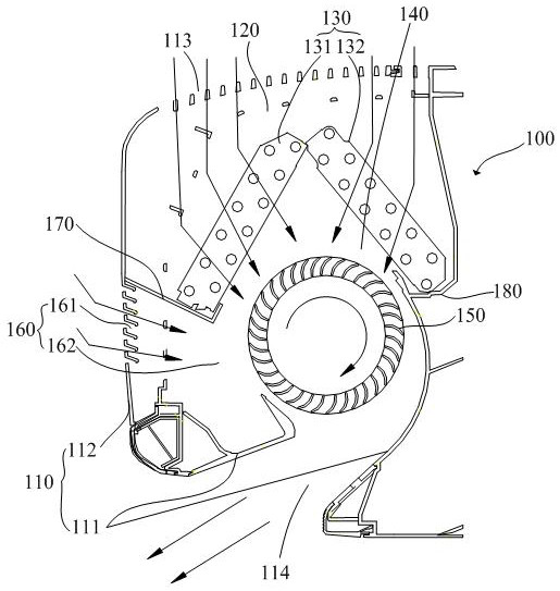
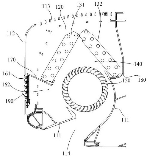
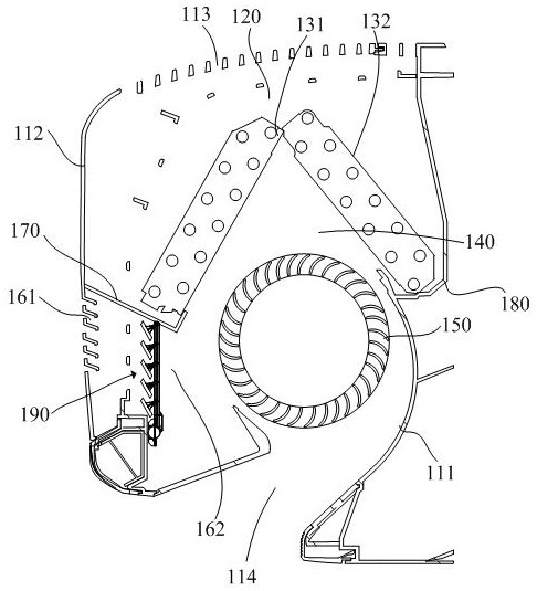
[0029] Refer figure 1 , figure 1 Illustrates an exemplary one kind of wall-mounted air conditioning indoor unit 100, 110 includes a heat exchange air inlet damper passage 120, heat exchanger housing 130, a heat exchange air passage air damper 140, fan 150 and a non-heat exchange air drainage duct 160; 110 generally comprises a housing 111 and a housing mounted on the skeleton front side 111 of the skeleton 112, 113 has an air inlet, an air outlet 114 is formed on the bobbin 111 forming the upper casing 112; heat exchange air passage inlet damper 120 formed in said housing in communication with the air inlet 113, constituting the indoor air inlet passage 130 and the heat transfer to be heat exchangers; exchanger 130 disposed in the...


PUM


Abstract

The invention provides a wall-mounted air conditioner indoor unit. The wall-mounted air conditioner indoor unit comprises a shell, a heat exchange air inlet duct, a heat exchanger, a heat exchange airoutlet duct, a fan and a non-heat exchange air drainage duct; the heat exchange air inlet duct is formed in the shell and communicates with an air inlet; the heat exchanger is arranged in the heat exchange air inlet duct; the heat exchange air outlet duct communicates with the heat exchange air inlet duct; the fan is arranged in the heat exchange air outlet duct; the non-heat exchange air drainage duct is separated from the air inlet and the heat exchange air inlet duct and comprises a drainage port and a drainage air duct; and the drainage air duct communicates with the drainage port and theheat exchange air outlet duct, so that indoor air flow entering through the drainage port is directly mixed with heat exchange air at the heat exchange air outlet duct. According to the wall-mountedair conditioner indoor unit, the outgoing air is softer, cool but not cold, and the comfort degree is improved; and the non-heat exchange air drainage air duct is separated from the heat exchange airinlet air duct, so that the air rush phenomenon is avoided, and the refrigerating performance and the heating performance of the product are not influenced.

Description

Technical field [0001] The present invention belongs to the technical field of air conditioning equipment, in particular a structure of a wall-mounted air conditioning indoor unit is improved. Background technique [0002] With the promotion and popularization of air conditioning concept of health, comfort requirements of users of air conditioning is increasing. Traditional air conditioner blowing strong, cold wind blowing straight, resulting in poor user experience, the air conditioning problem sick frequently. With the development of air-conditioning technology, the emergence of drainage technology, part of the upcoming indoor air drainage to the indoor unit, which is not part of the air flow through the indoor heat exchanger, known as non-air heat exchange, and through the indoor heat exchanger after heat exchange air mixed to form a mixed air, the air blowing from the indoor unit, not resorted to cool the cold. [0003] However, there are some limitations of the prior art, it...

Claims


Application Information

Patent Timeline
Patent Type & Authority Applications(China)
IPC IPC(8): F24F1/0057F24F13/04
CPCF24F1/0057F24F13/04
Inventor 徐超范强王伟孙兴朋赵海霞闫茂松
Owner QINGDAO HAIER SMART TECH R & D CO LTD
Learn More