Current sharing method of IGBT parallel circuit and IGBT parallel circuit

A circuit and parallel technology, applied in the direction of electrical components, output power conversion devices, etc., can solve problems such as uneven current, reduced service life, and poor circuit stability

Active Publication Date: 2020-11-27
苏州乾能电气有限公司
View PDF6 Cites 3 Cited by
  • Summary
  • Abstract
  • Description
  • Claims
  • Application Information

AI Technical Summary

Problems solved by technology

[0005] The object of the present invention is to provide a current sharing method, device, equipment, computer-readable storage medium and IGBT parallel circuit of an IGBT parallel circuit, so as to solve the uneven current flowing on each IGBT circuit in the IGBT parallel circuit in the prior art , resulting in poor overall circuit stability and reduced service life

Method used


Image

  • Current sharing method of IGBT parallel circuit and IGBT parallel circuit
  • Current sharing method of IGBT parallel circuit and IGBT parallel circuit
  • Current sharing method of IGBT parallel circuit and IGBT parallel circuit

Examples


specific Embodiment approach

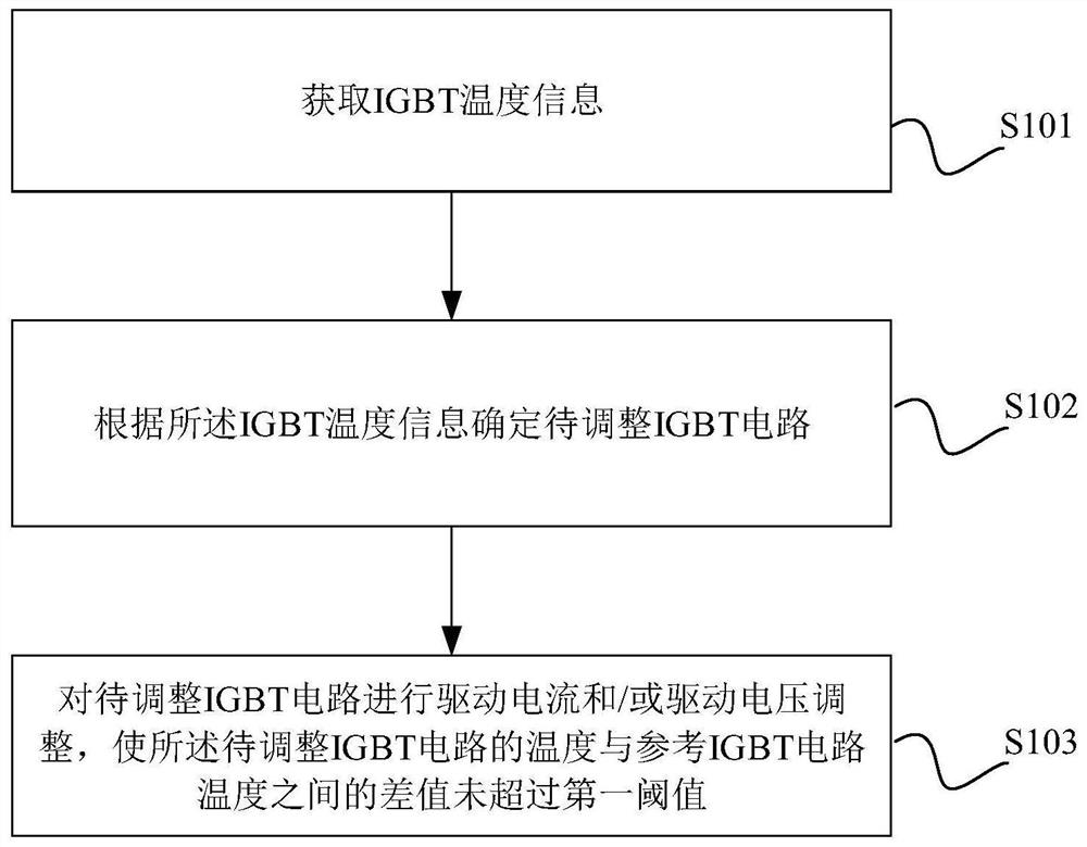
[0059] The core of the present invention is to provide a parallel circuit of the IGBT current sharing method, one of its particular embodiments schematic flow as figure 1 Shown, referred to as a specific embodiment, comprising:

[0060] S101: acquiring IGBT temperature information.

[0061] Since the parallel circuit of the IGBT having a plurality of IGBT circuit, the IGBT temperature IGBT information includes temperature information for each channel. The temperature information can be obtained by calculating the resistance value corresponding to the temperature measuring resistor NTC channel voltage by using AD.

[0062] S102: determining temperature information of the IGBT to be adjusted according to the IGBT circuit.

[0063] As a preferred embodiment, the circuit to be adjusted to a maximum temperature of IGBT IGBT circuit. Note that, in general, since we want the service life of the IGBT parallel circuit as long as possible, thus selecting the lower IGBT circuit current is la...

Embodiment approach

[0096] As a preferred embodiment, the adjustment module 300 includes:

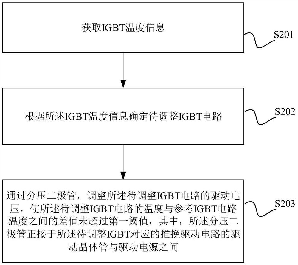
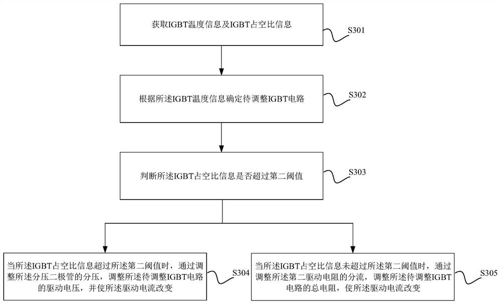
[0097] Current and voltage adjustment means for dividing via a diode, to be adjusted to adjust the voltage of the IGBT driving circuit, and changing the drive current, wherein the voltage divider diodes push-pull connected to the positive drive of the IGBT corresponding to be adjusted between the drive transistor and the drive power supply circuit;

[0098] and / or

[0099] By driving a second resistor to be adjusted to adjust the total resistance of the IGBT circuit, the drive current change, wherein the driving resistance of the second resistor connected in parallel with the first drive resistor.

[0100] As a preferred embodiment, the obtaining module 100 includes:

[0101] Duty ratio acquisition means for acquiring temperature information and IGBT IGBT duty cycle information;

[0102] Accordingly, the adjustment module 300 includes:

[0103] Determination means for determining whether the IGBT duty inform...


PUM


Abstract

The invention discloses a current sharing method of an IGBT parallel circuit. The current sharing method comprises the steps: obtaining IGBT temperature information; determining an IGBT circuit to beadjusted according to the IGBT temperature information; driving current and / or driving voltage adjustment is carried out on the IGBT circuit to be adjusted, wherein a difference value between the temperature of the IGBT circuit to be adjusted and the temperature of the reference IGBT circuit does not exceed a first threshold value. According to the method disclosed in the invention, the current inthe circuit is judged and compared through the temperature in the single IGBT circuit; the IGBT circuits to be adjusted are determined, the current flowing through the IGBT circuit to be adjusted ischanged, the temperature difference between the IGBT circuits is reduced, the working stability of the IGBT parallel circuit is ensured, and the service life of the IGBT parallel circuit is prolonged.The invention further provides a current sharing device and equipment of the IGBT parallel circuit, a computer readable storage medium and the IGBT parallel circuit, wherein the current sharing device and equipment have the beneficial effects.

Description

Technical field [0001] The present invention relates to the field of integrated circuit design applications, particularly to a parallel circuit of the IGBT current sharing method, apparatus, device, and computer readable storage medium IGBT parallel circuit. Background technique [0002] With the development of technology, integrated circuits, electronic devices have become more sophisticated, and ensure a stable and reliable work of complex integrated circuits, more and more attention outside the industry. [0003] In the power converter, inverter, and other products often use IGBT (insulated gate bipolar transistors) in parallel to meet the requirements of the current level, when the IGBT used in parallel, it is desirable ideally flowing through each of the IGBT currents are equal, in fact, they are not equal, parallel IGBT circuit in the same group, the current difference on each IGBT circuit will normally be about 20%, and should be noted that, the use of excessively high cur...

Claims


Application Information

Patent Timeline
Patent Type & Authority Applications(China)
IPC IPC(8): H02M1/088
CPCH02M1/088
Inventor 任晓峰王晓坤
Owner 苏州乾能电气有限公司
Why Eureka
Try Eureka