Novel solid-state relay and control method thereof

A solid-state relay and relay technology, applied in the fields of automation equipment and power electronics, can solve the problems of miscommunication, increase R&D costs, waste R&D costs, etc., and achieve the effect of meeting diversified needs

Pending Publication Date: 2020-11-27
唐山航清新能源有限公司
View PDF0 Cites 2 Cited by
  • Summary
  • Abstract
  • Description
  • Claims
  • Application Information

AI Technical Summary

Problems solved by technology

[0003] Although the existing solid-state relays have many advantages, they also have many shortcomings. For example, the existing solid-state relays can only be used in specific occasions. Better effect, when AC and DC exist at the same time, only two or more relays can be selected, which wastes space and research and development costs. At the same time, the rated power of the solid state relay between users is often required to derate the load power during use. As a result, the user's cost of use has increased; at the same time, the solid state relay has a greater sensitivity to overload, and it must be protected against overload with a fast fuse or RC damping circuit
This increases the volume of the equipment, increases the cost of research and development, and reduces the efficiency
Moreover, after the semiconductor device is turned off, there may still be a leakage current of several microamperes to several milliamperes, so ideal electrical isolation cannot be achieved, and false conduction may occur. These problems affect the design of the research and development personnel and reduce the reliability of the relay. , availability, controllability

Method used


Image

  • Novel solid-state relay and control method thereof
  • Novel solid-state relay and control method thereof
  • Novel solid-state relay and control method thereof

Examples


Embodiment Construction

[0027] Reference will now be made in detail to the exemplary embodiments, examples of which are illustrated in the accompanying drawings. When the following description refers to the accompanying drawings, the same numerals in different drawings refer to the same or similar elements unless otherwise indicated. The implementations described in the following exemplary examples do not represent all implementations consistent with the present disclosure. Rather, they are merely examples of apparatuses and methods consistent with aspects of the presently disclosed embodiments as recited in the appended claims.

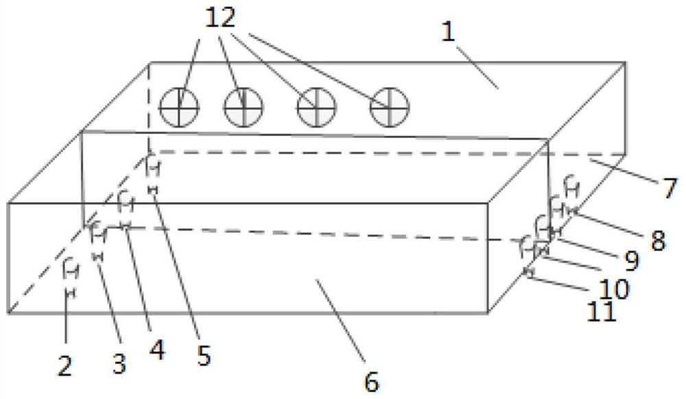
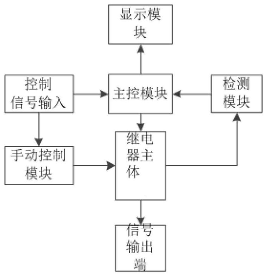
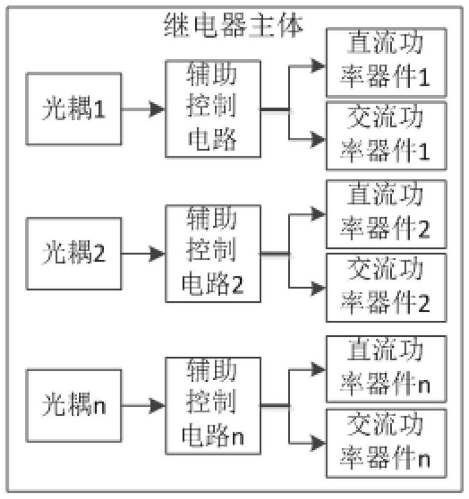
[0028] see Figure 1-2 , in the embodiment of the present invention, a new type of solid state relay, including a relay body and a relay housing 1 encapsulating the relay body, the relay body is respectively connected with a signal output terminal, a detection module and a control system, and the detection module is used to detect the relay The connected state of each cir...


PUM


Abstract

The invention relates to the technical field of power electronics and the field of automation equipment, in particular to a novel solid-state relay and a control method thereof. The novel solid-staterelay comprises a relay main body and a relay shell for packaging the relay main body, and the relay main body is connected with a signal output end, a detection module and a control system. The detection module is used for detecting the connection state of the relay main body, feeding back the detection data to the control system and controlling the input and received control signal to be transmitted to the control system, and the control system controls the relay main body to output a related electric signal according to the received control signal, the electric signal drives a load throughthe signal output end, and the control system controls the power of the electric signal output by the relay main body according to detection data fed back by the detection module. The novel solid-state relay and the control method thereof have the beneficial effects that the problem that alternating current and direct current cannot be shared is solved, and the alternating current and the direct current can be shared or used separately without replacing the relay; facility for meeting requirements of users.

Description

technical field [0001] The invention relates to the field of power electronics technology and the field of automation equipment, in particular to a novel solid-state relay and a control method thereof. Background technique [0002] With the development of power electronics technology, relays have been widely used in various fields, and solid-state relays have gradually replaced electromagnetic relays and become mainstream relays. Solid State Relay (Solid State Relay), referred to as SSR, is an "integrated" non-contact electronic switching device composed of integrated circuits and discrete components. It uses electronic circuits to realize the function of relays, relying on photocouplers (or Other coupling methods) to achieve electrical isolation between the control system (input loop) and the controlled system (output loop). Since there is no mechanical contact part in the switching process, it has the outstanding advantages of small control power, high reliability, long l...

Claims


Application Information

Patent Timeline
Patent Type & Authority Applications(China)
IPC IPC(8): H03K17/78
CPCH03K17/78
Inventor 赵作有张治朝
Owner 唐山航清新能源有限公司
Why Eureka
Try Eureka