Gasket polishing equipment for hardware tool machining

A hardware tool and gasket technology, which is applied in the field of gasket polishing equipment for hardware tool processing, can solve the problems of manpower consumption, cumbersome operation process, and low work efficiency, and achieve the effects of improving work efficiency, simple operation, and saving manpower

Active Publication Date: 2020-12-01
山东东泰磨具有限公司
View PDF10 Cites 9 Cited by
  • Summary
  • Abstract
  • Description
  • Claims
  • Application Information

AI Technical Summary

Problems solved by technology

[0006] In order to overcome the disadvantages of the above-mentioned method, such as cumbersome operation process, low work efficiency, and relatively labor-intensive operation, the techn

Method used


Image

  • Gasket polishing equipment for hardware tool machining
  • Gasket polishing equipment for hardware tool machining
  • Gasket polishing equipment for hardware tool machining

Examples


Embodiment 1

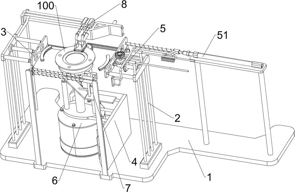
[0024] A pad polishing equipment for hardware tool processing, such as Figure 1-3 As shown, it includes a base 1, a mounting frame 2, a slide plate 3 and a first fixing frame 4. The mounting frame 2 is connected to the left and right sides of the top of the base 1, and the sliding plate 3 is slidably connected to the mounting frame 2, and the two sides are installed The top of the base 1 between the frames 2 is connected with a first fixed frame 4, and also includes a transposition assembly 5 and a rotation assembly 6. A transposition assembly 5 is provided between the mounting frame 2, the base 1 and the slide plate 3, and the first A rotating assembly 6 is provided between the fixed frame 4 , the base 1 and the sliding plate 3 .

[0025] The transposition assembly 5 includes a cylinder 51, a first sliding frame 52, a first compression spring 53, a driving rack 54, an inner diamond sleeve 55, a clamping ring 56, a rotating shaft 57, a bevel gear 58 and a one-way gear 59, bas...

Embodiment 2

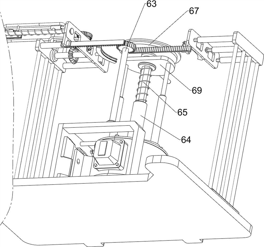
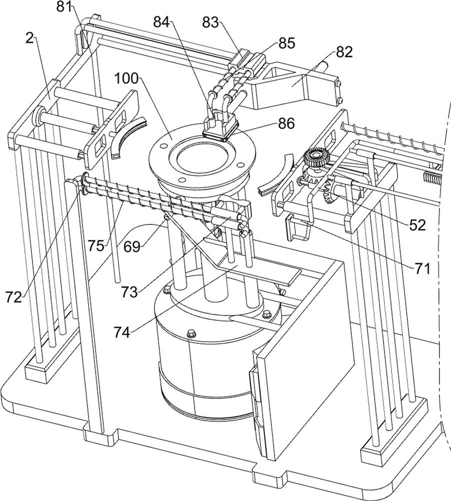
[0029] On the basis of Example 1, such as Figure 4 As shown, the pressing assembly 7 is also included, and the pressing assembly 7 includes a connecting frame 71, a guide rail 72, a second sliding frame 73, an extrusion plate 74 and an elastic member 75, and the connecting frame 71 is connected to the first sliding frame 52. A guide rail 72 is connected to the front side of the top of the base 1, and a second sliding frame 73 is slidably connected to the guide rail 72. An elastic member 75 is connected between the second sliding frame 73 and the guide rail 72. The second sliding frame 73 and the connecting frame 71 In cooperation, the bottom of the second sliding frame 73 is connected with an extruding plate 74, and the extruding plate 74 cooperates with the elevating frame 69.

[0030]When the first sliding frame 52 moves to the left, it drives the connecting frame 71 to move to the left. When the connecting frame 71 moves to the left to contact with the second sliding frame...


PUM


Abstract

The invention relates to polishing equipment, in particular to gasket polishing equipment for hardware tool machining. The technical aim to be achieved by the invention is how to design the gasket polishing equipment for hardware tool machining, wherein the equipment is simple to operate, can improve the working efficiency and saves manpower. In order to achieve the technical purpose, the gasket polishing equipment for hardware tool machining comprises a base, a first fixing frame, a transposition assembly and a rotating assembly. Mounting frames are connected to the two sides of the top of the base, and sliding plates are connected to the mounting frames in a sliding mode; the first fixing frame is connected to the position, between the mounting frames on the two sides, of the top of thebase; the transposition assembly is arranged among the mounting frames, the base and the sliding plates; and the rotating assembly is arranged among the first fixing frame, the base and the sliding plates. According to the gasket polishing equipment, the transposition assembly, the rotating assembly and the polishing assembly are matched to polish gaskets, and therefore the effect of polishing thegaskets is achieved.

Description

technical field [0001] The invention relates to a polishing device, in particular to a gasket polishing device for processing hardware tools. Background technique [0002] In the construction industry of modern society, hardware tools are a relatively important part. Hardware tools are usually a general term for various metal devices manufactured by using iron, steel, aluminum and other metals through physical processing such as forging, rolling, and cutting. Hardware tools can be divided into tool hardware, construction hardware and daily hardware, etc. Gaskets are a kind of hardware tools. When gaskets are processed, they usually need to be polished, and then put into use after polishing. [0003] At present, the way of polishing the gasket is usually to manually hold the gasket with one hand, and hold the polishing sheet with the other hand, and then make the polishing sheet contact the gasket, and then rotate the gasket, so as to polish the gasket. The operation process ...

Claims


Application Information

Patent Timeline
IPC IPC(8): B24B29/02B24B41/00B24B41/02B24B41/06
CPCB24B29/02B24B41/00B24B41/02B24B41/06
Inventor 王美慧
Owner 山东东泰磨具有限公司
Why Eureka
Try Eureka