Industrial robot tray grabbing height intelligent detection method

An industrial robot and intelligent detection technology, applied in manipulators, manufacturing tools, etc., can solve problems such as increased production costs, system errors, and production stagnation, and achieve the effects of controlling production costs, high robustness, and easy replication

Pending Publication Date: 2020-12-01
埃华路(芜湖)机器人工程有限公司
0 Cites 1 Cited by

AI-Extracted Technical Summary

Problems solved by technology

At present, the industry mainly uses the 3D vision system for positioning, identification and positioning. This system has high cost and high requirements for the robot itself, which increases the production cost; another solution is to directly use the laser distance sensor to detect the height, and the specific value of the height is obtained as...

Abstract

The invention relates to an industrial robot tray grabbing height intelligent detection method. The method utilizes a photoelectric distance sensor installed on a robot gripper for detection, and thedetection method comprises the following steps: placing a partition plate on the ground, moving a robot to a partition plate grabbing point, and recording a teaching grabbing point P1; setting an induction distance H of the photoelectric distance sensor; executing a search program through the robot, and recording the current sensing position P2 of the robot when the signal of the photoelectric distance sensor becomes a high-level signal; obtaining a mapping relation X through P1 and P2; grabbing the partition plate with the unknown height, executing a third operation step, and recording a current induction position P3; and sixthly, obtaining a grabbing position coordinate Px according to the combination of X and P3, wherein the coordinate Px is a final grabbing position coordinate. According to the method, a 3D vision system and a laser distance sensor do not need to be matched with distance measurement grabbing, the production cost is effectively controlled, and meanwhile the system is stable in operation, high in robustness and easy to copy in a project.

Application Domain

Technology Topic

Image

  • Industrial robot tray grabbing height intelligent detection method
  • Industrial robot tray grabbing height intelligent detection method

Examples

  • Experimental program(1)

Example Embodiment

[0018] In order to make those skilled in the art better understand the technical solutions of the present invention, the present invention will be described more clearly and completely below with reference to the accompanying drawings in the embodiments. Of course, the described embodiments are only a part of the present invention. Not all, based on this embodiment, other embodiments obtained by those skilled in the art without creative labor are all within the protection scope of the present invention.
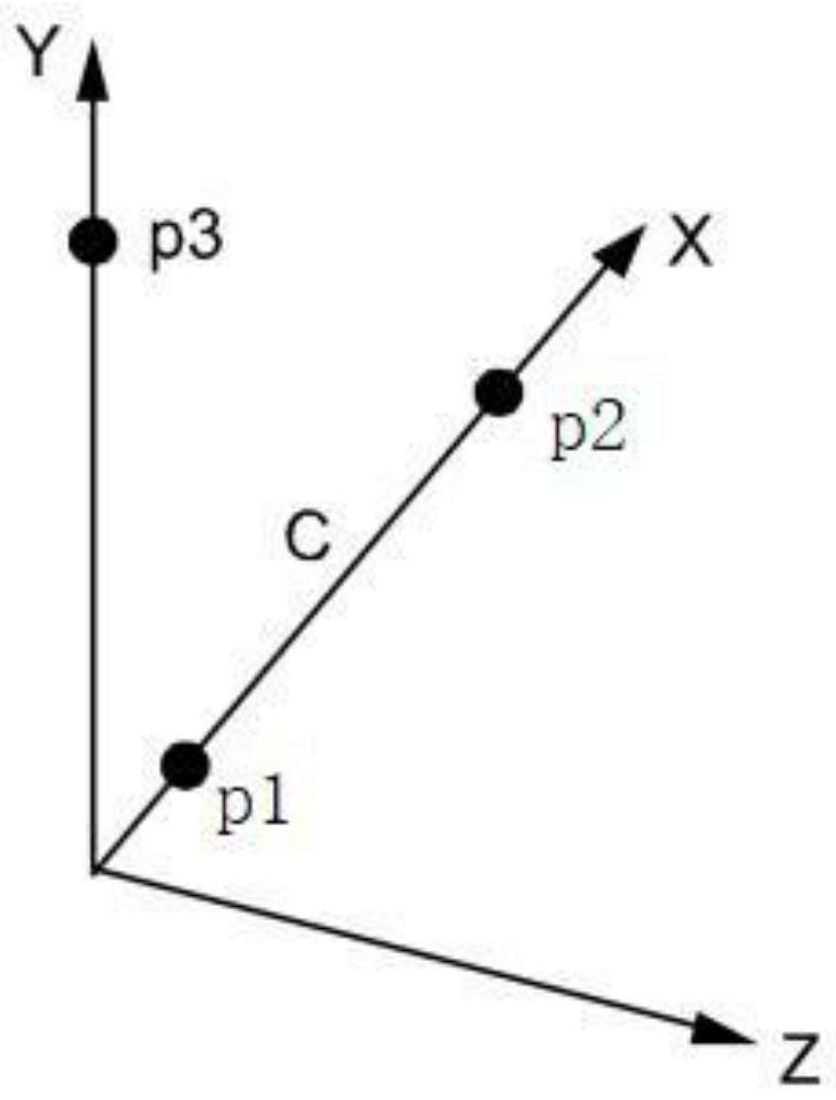
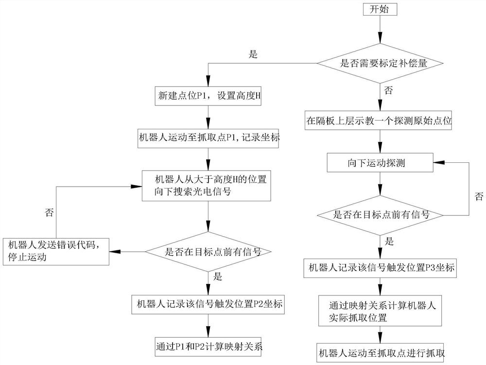
[0019] like Figure 1 to Figure 2 As shown in the figure, an intelligent detection method for the grasping height of an industrial robot pallet, the method utilizes a photoelectric distance sensor installed on the robot gripper for detection, and the detection method includes the following steps:
[0020] Step 1: Place a clapboard on the ground, move the robot to the clapboard grab point, and record the teach grab point P 1 (x 1 ,y 1 ,z 1 ,a 1 ,b 1 ,c 1 );
[0021] Step 2: Set the sensing distance H of the photoelectric distance sensor; the sensing distance H can be adjusted according to the actual situation;
[0022] Step 3: The robot executes the search program. When the photoelectric distance sensor signal changes from a low-level signal to a high-level signal, the robot stops the search program and records the current sensing position of the robot as follows:
[0023] P 2 (x 2 ,y 2 ,z 2 ,a 2 ,b 2 ,c 2 ); if no high-level signal is found, the robot sends an error code, stops motion, and then searches again;
[0024] Step 4: Grab point P by teaching 1 and the sensing position P 2 Obtain the mapping relationship between the robot world coordinates and the actual grasping coordinates X=z 2 -z 1; The sensing distance H of the photoelectric distance sensor is not equal to the distance in the robot coordinate system, so the mapping relationship X is calculated to make the sensing distance H conform to the distance in the robot coordinate system; since X is the position of the mapping sensor in the robot world coordinates, so X remains unchanged and is applicable to any height of the clapboard to be grasped;
[0025] Step 5: Grab the clapboard of unknown height, and the robot performs the third operation steps to record the current sensing position P of the robot 3 (x 3 ,y 3 ,z 3 ,a 3 ,b 3 ,c 3 );
[0026] Step 6: According to the mapping relationship X and P 3 Combined, the grab position coordinates are obtained as follows:
[0027] Px(x 1 ,y 1 ,z 3 -X,a 1 ,b 1 ,c 1 ),
[0028] The coordinate Px is the final grab position coordinate.
[0029] When the robot executes the search program, it descends at a constant speed from the height above the partition above H, and searches for the signal of the photoelectric distance sensor; when the height of the photoelectric distance sensor above the partition is greater than H, it is a low-level signal, and when the photoelectric distance sensor is less than H, it suddenly changes. It is a high level signal, the robot stops;
[0030] Taking the sensing distance H as 100 mm as an example, the robot executes the search procedure. The robot descends at a speed of 10 mm per second from a height of 120 mm above the partition. When the photoelectric distance sensor signal changes from a low-level signal to a high-level signal After receiving the signal, the robot stops searching for the program and records the current sensing position P of the robot; according to the sensing position P and the mapping relationship X, the actual grasping coordinates of the robot are calculated, and the robot is adjusted to the actual grasping coordinate position to carry out grasping operations.
[0031] like figure 1 As shown, it is the robot world coordinate system, X, Y, Z represent three directions, where P 1 is the first point in the X-axis direction, P 2 is the second point in the X-axis direction; the sensing beam of the photoelectric distance sensor installed on the robot arm is emitted along the X-axis square, and the robot starts from the origin and moves in the positive direction of the X-axis to P 1 point, the P 1 Points are recorded as teaching grab points;
[0032] The robot executes the search program and moves along the positive direction of the X axis to P 2 point, receive the high-level signal from the photoelectric distance sensor, record P 2 point position, via P 1 Point coordinates and P 2 The point coordinate calculation is the mapping relationship C between the robot world coordinate system and the detection distance of the distance sensor, and the mapping relationship C is figure 1 The distance difference between points P1 and P2 shown in 3 Click to calculate the actual grab position.
[0033] The foregoing has shown and described the basic principles, main features and advantages of the present invention. Those skilled in the art should understand that the present invention is not limited by the above-mentioned embodiments. The above-mentioned embodiments and descriptions describe only the principles of the present invention. Without departing from the spirit and scope of the present invention, the present invention will also have various Such changes and improvements fall within the claimed invention. The claimed scope of the present invention is defined by the appended claims and their equivalents.

PUM

no PUM

Description & Claims & Application Information

We can also present the details of the Description, Claims and Application information to help users get a comprehensive understanding of the technical details of the patent, such as background art, summary of invention, brief description of drawings, description of embodiments, and other original content. On the other hand, users can also determine the specific scope of protection of the technology through the list of claims; as well as understand the changes in the life cycle of the technology with the presentation of the patent timeline. Login to view more.

Similar technology patents

Modular high-temperature material digestion system

PendingCN112551920ASimple operation and controlControl production costsGas treatmentDispersed particle separationCircular economyProcess engineering
Owner:LOESCHE (SHANGHAI) CO LTD

Method for preparing high-purity superfine zinc sulfide

InactiveCN101624210AControl production costsAvoid environmental pollutionZinc sulfidesAmmonium sulphideTM compound
Owner:黄石市高纯化工技术有限公司

Electronic equipment

Owner:GUANGDONG OPPO MOBILE TELECOMM CORP LTD

Light source device and projector

InactiveCN105954964AImprove light utilization efficiencyControl production costsProjectorsEngineeringLight source
Owner:QISDA OPTRONICS (SUZHOU) CO LTD +1

Method for completely depolymerizing polytetrahydrofuran in anhydrous environment

PendingCN112961122AControl production costsOrganic chemistrySulfuric acidTetrahydrofuran
Owner:XINJIANG BLUE RIDGE TUNHE ENERGY

Classification and recommendation of technical efficacy words

  • Control production costs
  • Run smoothly

Anti-delamination special coated sand and preparation method thereof

ActiveCN105750476AReduced volume reduction tendencyControl production costsFoundry mouldsFoundry coresBrown iron oxideAqueous solution
Owner:QINGLING MOTORS GRP

Production method of 180-level polyurethane wire enamel

ActiveCN104017476AControl production costsReduce energy consumptionPolyurea/polyurethane coatingsChemistryMethylene diphenyl diisocyanate
Owner:NANTONG BAICHUAN NEW MATERIAL CO LTD +2

Preparation method of ritodrine

ActiveCN103113238AHigh chemoselectivityControl production costsOrganic compound preparationAmino-hyroxy compound preparationHydrochlorideChloride
Owner:SUZHOU LIXIN PHARMA
Why Eureka
Try Eureka