An energy-saving concrete mixing device
A concrete and energy-saving technology, which is applied in the direction of clay preparation device, control device, unloading device, etc., can solve the problems of low energy saving and too many motors, and achieve the effects of energy saving, convenient use of equipment, and convenient use of equipment
- Summary
- Abstract
- Description
- Claims
- Application Information
AI Technical Summary
Problems solved by technology
Method used
Image
Examples
Embodiment 1
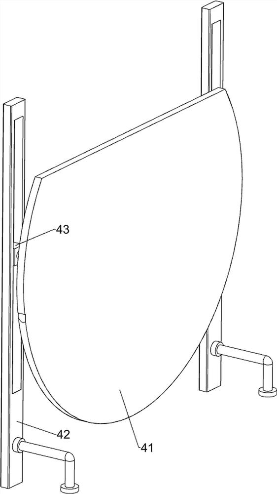
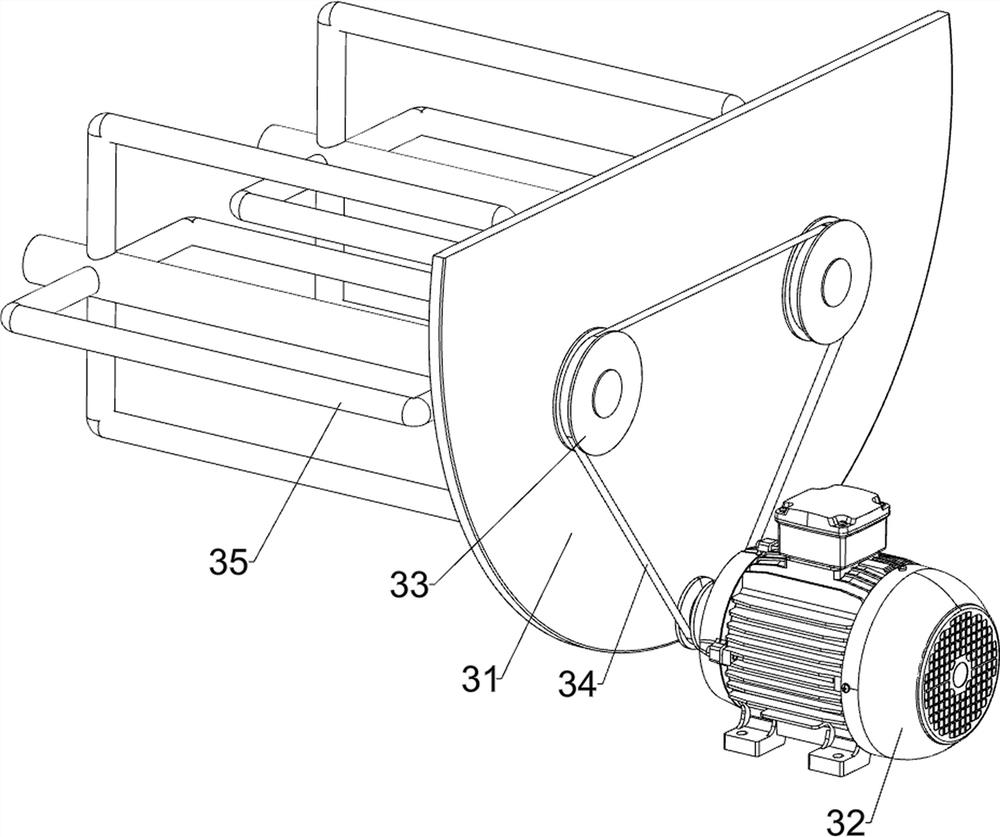
[0020] An energy-saving concrete mixing device, such as Figure 1-3 As shown, it includes a bottom plate 1, a cylinder 2, a stirring assembly 3 and a sliding discharge assembly 4. The top of the bottom plate 1 is fixed with a cylinder 2 through bolts, and the right side of the bottom plate 1 and the cylinder 2 are installed with a stirring The mixing assembly 3 is equipped with a sliding discharge assembly 4 on the left side of the cylinder 2.
[0021] When it is necessary to use this device for concrete mixing, the material is placed in the cylinder 2 through the through hole on the upper right side of the cylinder 2, and then the mixing component 3 is controlled to start working to prepare the concrete. After the concrete preparation is completed, the control The mixing assembly 3 stops working, and then the prepared concrete is released by sliding the discharging assembly 4 .
[0022] The mixing assembly 3 includes a mounting plate 31, a reduction motor 32, a first pulley ...
Embodiment 2
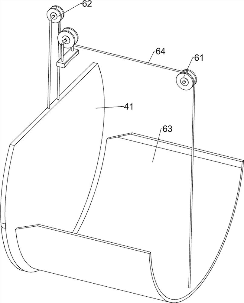
[0027] On the basis of Example 1, such as figure 1 , 4 As shown in and 5, a control assembly 5 is also included, and a control assembly 5 is connected between the front side of the sliding discharge assembly 4, the top front side of the bottom plate 1, and the stirring assembly 3, and the control assembly 5 includes a first hollow tube 51, a screw mandrel 53, the second pulley 54, the second flat belt 55, the nut 56, the piston plate 57, the second hollow pipe 58, the connecting pipe 59 and the piston rod 510, the front side of the top of the base plate 1 is fixed with the first hollow pipe 51 by bolts, The right part of the front side of the first hollow tube 51 has a word hole 52, and the rotation type is provided with a screw mandrel 53 in the first hollow tube 51, and the right end of the screw mandrel 53 and the right side of the first pulley 33 on the front side are all provided with a second pulley 54 , a second flat belt 55 is wound between the second pulleys 54, a nu...
PUM
 Abstract
Description
Claims
Application Information
 - R&D
- Intellectual Property
- Life Sciences
- Materials
- Tech Scout
- Unparalleled Data Quality
- Higher Quality Content
- 60% Fewer Hallucinations
Browse by: Latest US Patents, China's latest patents, Technical Efficacy Thesaurus, Application Domain, Technology Topic, Popular Technical Reports.
© 2025 PatSnap. All rights reserved.Legal|Privacy policy|Modern Slavery Act Transparency Statement|Sitemap|About US| Contact US: help@patsnap.com


