Anti-roll adjustable hydro-pneumatic suspension hydraulic system

A technology of hydraulic system and oil and gas suspension, applied in the field of anti-roll adjustable oil and gas suspension hydraulic system, to achieve the effect of ensuring stability, reasonable structure and reliable operation

Active Publication Date: 2020-12-01
泰安航天特种车有限公司
View PDF11 Cites 8 Cited by
  • Summary
  • Abstract
  • Description
  • Claims
  • Application Information

AI Technical Summary

Problems solved by technology

[0004] The purpose of the present invention is to provide an anti-rolling adjustable oil-pneumatic suspension hydraulic system, which solves the stability problem of the speed control of the suspension cylinder when it bears a heavy load and descends, and at the same time ensures that the hydraulic system can withstand the vehicle suspension when the hydraulic system is not in action. The load borne by the rack system prevents the hydraulic system from overloading, thus protecting the hydraulic system and the vehicle safety

Method used


Image

  • Anti-roll adjustable hydro-pneumatic suspension hydraulic system
  • Anti-roll adjustable hydro-pneumatic suspension hydraulic system
  • Anti-roll adjustable hydro-pneumatic suspension hydraulic system

Examples


Embodiment 1

[0032] Example 1: Anti-rolling adjustable oil-pneumatic suspension hydraulic system for a two-axle vehicle

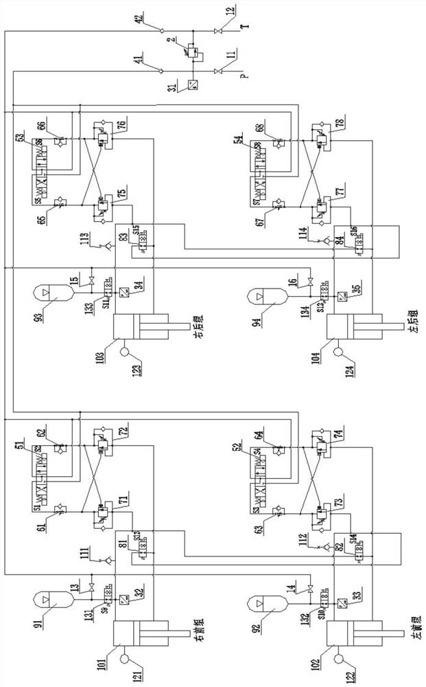
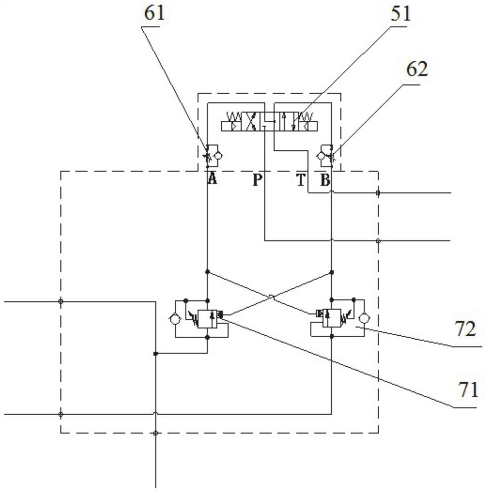
[0033] An anti-rolling adjustable oil-pneumatic suspension hydraulic system, including a front suspension hydraulic control unit, a rear suspension hydraulic control unit and an oil pipeline, and the front suspension hydraulic control unit includes a right front group suspension control mechanism and a left front group suspension The control mechanism, the rear suspension hydraulic control unit includes the right rear group suspension control mechanism and the left rear group suspension control mechanism, the front suspension hydraulic control unit and the rear suspension hydraulic control unit respectively correspond to one axle on the vehicle, through The oil pipeline includes the main oil inlet pipe, the main oil return pipe, and the pipes connecting the inside and between the front suspension hydraulic control unit and the rear suspension hydraulic control unit; a cu...

Embodiment 2

[0065] Example 2: Multi-axle vehicle roll adjustable oil-pneumatic suspension hydraulic system

[0066] The principle described in Embodiment 1 is also applicable to multi-axle vehicles, such as Figure 4 In the oil-pneumatic suspension hydraulic system of the three-axle vehicle, the right front oil cylinder 101 represents the right suspension oil cylinder of the first axle, the left front oil cylinder 102 represents the left suspension oil cylinder of the first axle, and the right rear oil cylinder 105 represents the right suspension oil cylinder of the second axle. The right rear oil cylinder 103 represents the right side suspension oil cylinder of the third axle, the left front oil cylinder 106 represents the left side suspension oil cylinder of the second axle, and the left front oil cylinder 104 represents the left side suspension oil cylinder of the third axle.

[0067] The rod cavity and the rodless chamber of the right rear oil cylinder 105,103 of the second axle right...


PUM


Abstract

The invention discloses an anti-roll adjustable hydro-pneumatic suspension hydraulic system which comprises a suspension hydraulic control unit and an oil pipeline which are arranged on each axle, each suspension hydraulic control unit comprises two groups of suspension control mechanisms on the left side and the right side respectively, and each suspension control mechanism comprises an oil cylinder, a valve piece, a pipeline and an energy accumulator; a rod cavity of an oil cylinder on one side of each suspension hydraulic control unit is communicated with a rodless cavity oil way on the other side of the same unit through a valve piece and a pipeline, and a rodless cavity of each oil cylinder is connected with an energy accumulator of the suspension control mechanism in the same set through a valve piece. The stability of speed control when the suspension oil cylinder bears large load and descends is achieved; meanwhile, the suspension oil cylinder can bear the load borne by a suspension system when a hydraulic system does not act, the hydraulic system is prevented from being overloaded, so that the safety of the hydraulic system and the whole vehicle is protected; vehicle posture adjustment and speed adjustment such as vehicle body lifting, front-back pitching, left-right inclining and vehicle body leveling can be achieved.

Description

technical field [0001] The invention relates to the technical field of automobile suspension, in particular to an anti-rolling adjustable oil-pneumatic suspension hydraulic system. Background technique [0002] The use of oil-pneumatic suspension is an important way to improve the ride comfort, passability and fuel economy of the car. Good ride comfort generally requires oil-pneumatic springs with low stiffness, but this will cause the vehicle body to tilt sharply when driving on a curve. On the one hand, it makes the occupants feel uncomfortable, and on the other hand, it changes the steering characteristics of the car, thereby reducing the driving stability of the car. Generally, the suspension increases the roll angle stiffness by adding a special lateral stabilizer (such as a stabilizer bar). However, this method makes the structural design of the suspension system more complicated. [0003] China Invention Patent Authorization Announcement No. CN102059929B (Patent Appl...

Claims


Application Information

Patent Timeline
IPC IPC(8): B60G17/015B60G17/0165B60G17/018B60G17/08B60G21/06
CPCB60G17/0152B60G17/0165B60G17/018B60G17/08B60G21/06B60G2204/8304B60G2200/34B60G2202/24B60G2800/01B60G2800/20B60G2800/912B60G2800/914B60G2300/02B60G2300/09
Inventor 禹东方杜宏斌朱学斌程锐杨立荣周桂凤孙启甲王瑞于庆芬巩丽琴李大鹏刘富宝刘凤华杨春梅
Owner 泰安航天特种车有限公司
Why Eureka
Try Eureka