
Independent suspension system and crane with the independent suspension system

A technology of independent suspension and frame, which is used in construction cranes, suspensions, elastic suspensions, etc., can solve the problems of poor force characteristics, poor trafficability, and impact on service life.

Active Publication Date: 2017-02-15
XUZHOU HEAVY MASCH CO LTD
View PDF8 Cites 1 Cited by
  • Summary
  • Abstract
  • Description
  • Claims
  • Application Information

AI Technical Summary

Problems solved by technology

[0007] First of all, the side of the guide sleeve of the suspension cylinder is connected to the frame, and the lower end of the piston rod is connected to the wheel edge. The weight of the vehicle body and the reaction force applied to the tire by the ground all act on the suspension cylinder, which has poor force characteristics and affects the service life.
[0008] Secondly, the entire steering mechanism is installed above the main reducer, which cannot effectively control the minimum clearance between the main reducer and the ground, resulting in poor trafficability.

Method used


Image

  • Independent suspension system and crane with the independent suspension system
  • Independent suspension system and crane with the independent suspension system
  • Independent suspension system and crane with the independent suspension system

Examples


Embodiment Construction

[0039] The core of the present invention is to provide an independent suspension system, which reduces the radial load on the suspension oil cylinder, provides a reliable guarantee for the independent movement of the left and right wheels, improves the control stability of the whole machine, and reduces maintenance costs. The present embodiment will be described in detail below in conjunction with the accompanying drawings.

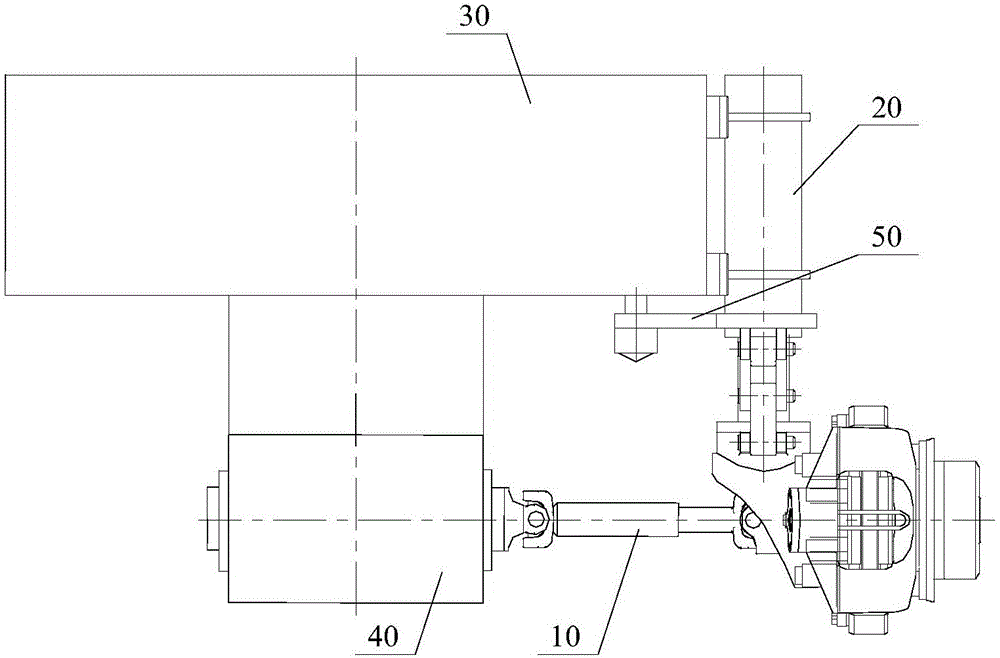
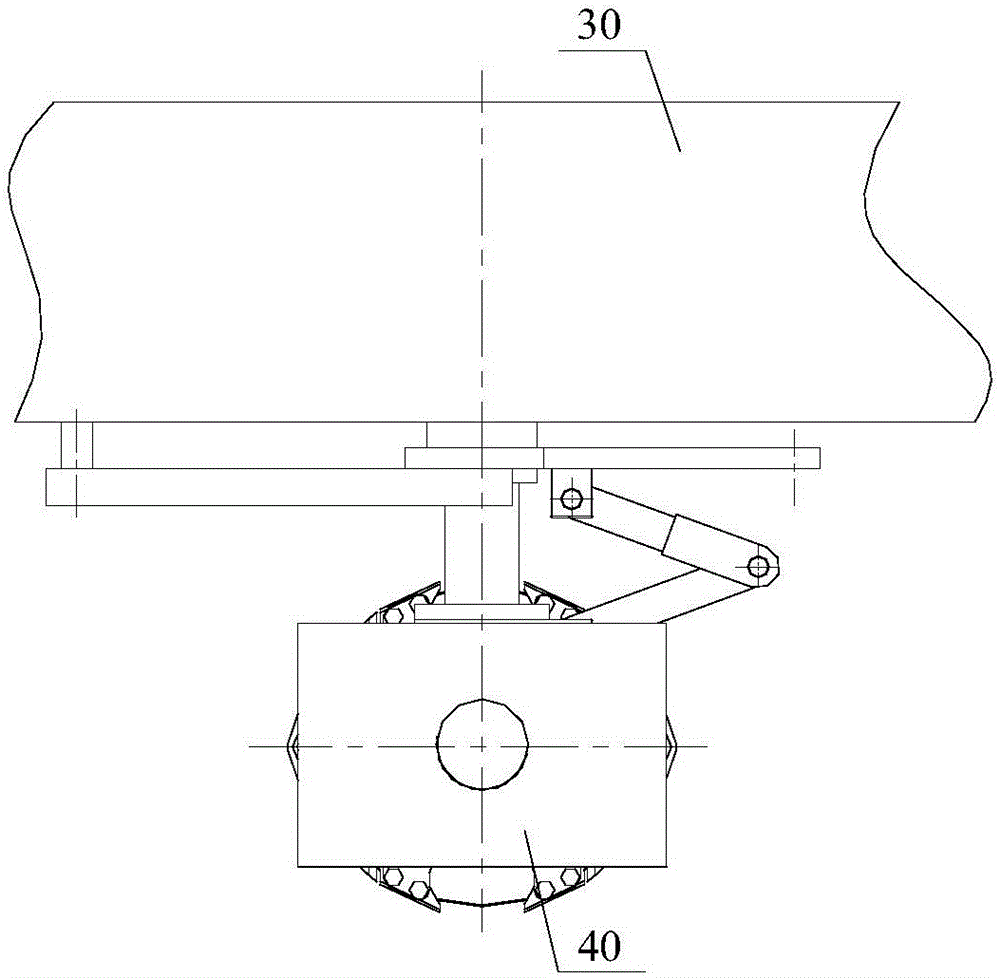
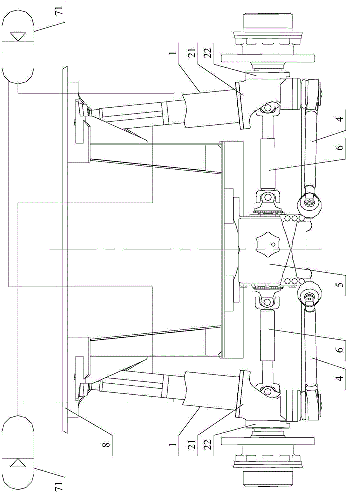
[0040] See image 3 and Figure 4 ,in, image 3 It is a front view of the independent suspension system described in this embodiment, which is a view formed from the front and rear directions, Figure 4 It is a top view of the independent suspension system in this embodiment.

[0041] Without loss of generality, this proposal takes the steering drive shaft as the main body for detailed description. It should be understood that the steering drive function does not constitute a limitation on the independent suspension system.

[0042] The two suspension...


PUM


Abstract

The invention discloses an independent suspension system, comprising: two suspension oil cylinders, respectively arranged between the wheel edges of the wheels on both sides and the vehicle frame; a steering mechanism, used to drive the wheels on both sides to turn under the drive of the steering power cylinder; It also includes two swing rods corresponding to the wheels on both sides, one end of each swing rod is hinged with the wheel edge of the corresponding side wheel through a ball hinge, and the other end of the swing rod is hinged with the wheel edge of the corresponding side wheel through two ball hinges. The front and rear directions are respectively hinged with the fixing member fixed under the final reducer. The invention realizes the positioning of the tire mounted on the wheel edge through structural improvement, ensures that the movement of the tire meets the design requirements during the running of the crane, and can completely avoid the possible destructive influence of the suspension cylinder, thereby reliably realizing the alignment of the left and right wheels. They move independently of each other, make full use of the adhesion conditions of the road surface, and greatly improve the control stability of the whole machine. On this basis, the present invention also provides a crane with the independent suspension system.

Description

technical field [0001] The invention relates to the technical field of engineering machinery, in particular to an independent suspension system and a crane with the independent suspension system. Background technique [0002] As we all know, for large heavy-duty all-terrain construction machinery, the driving stability of its chassis directly affects the operation performance of the whole machine. In addition to the chassis power system, its suspension system is a key factor affecting driving stability. [0003] Taking the chassis suspension system of an all-terrain crane as an example, traditional rigid bridges are commonly used. According to the structural characteristics of the guiding mechanism, it is mainly divided into two categories: non-independent suspension and independent suspension; among them, the left and right wheels of the non-independent suspension are mounted on an integral rigid shaft or the axle housing of the non-disconnected drive axle. The independen...

Claims


Application Information

Patent Timeline
Patent Type & Authority Patents(China)
IPC IPC(8): B60G13/14B60G13/08B62D5/20B62D7/06
CPCB60G3/06B60G11/265B60G2200/142B60G2300/06B62D7/08B62D7/144B60G7/003B60G2204/128B60G2204/416B60G15/12B60G3/20B60G13/08B60G13/005B60G21/05B62D5/06B66C9/00
Inventor 丁宏刚李丽朱磊马云旺宋建军马飞
Owner XUZHOU HEAVY MASCH CO LTD
Learn More