Cable laying system with adjustable winding radius for electric power engineering

A technology for power engineering and cable laying, applied in the field of power engineering, can solve problems such as increased labor and aggravated cable wear, and achieve the effects of saving labor, avoiding excessive bending damage, and expanding the scope of application

Inactive Publication Date: 2020-12-01
张乙顺
View PDF0 Cites 2 Cited by
  • Summary
  • Abstract
  • Description
  • Claims
  • Application Information

AI Technical Summary

Problems solved by technology

[0003] The purpose of the present invention is to provide a cable laying system for electric power engineering with adjustable winding radius, to solve the problem in the background technology mentioned above and most of the prior art are transported by manually dragging cables, which increases the labor, exacerbating the problem of cable wear

Method used


Image

  • Cable laying system with adjustable winding radius for electric power engineering
  • Cable laying system with adjustable winding radius for electric power engineering
  • Cable laying system with adjustable winding radius for electric power engineering

Examples


Embodiment 1

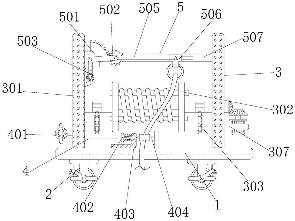
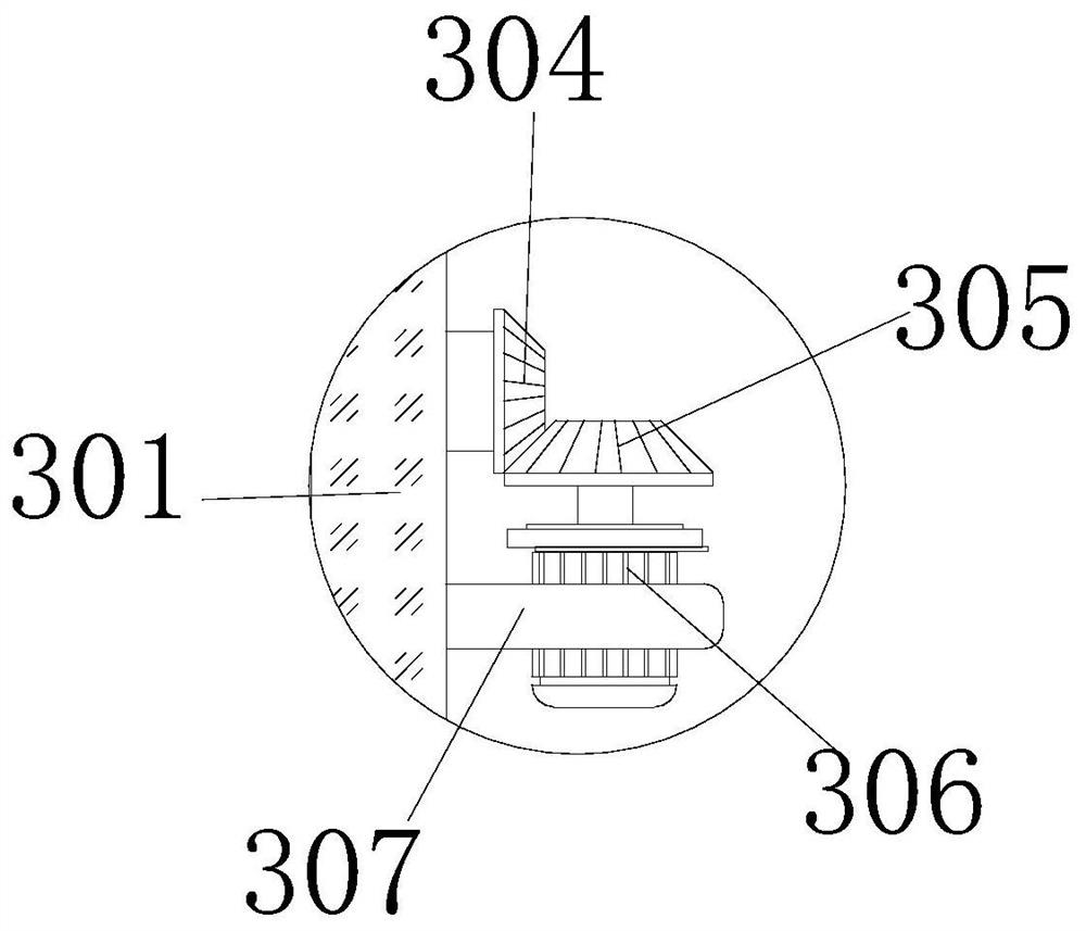
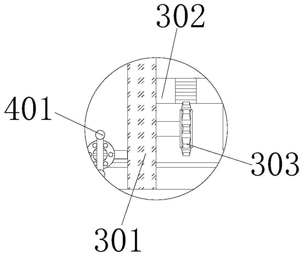
[0041] A cable laying system for power engineering with adjustable winding radius, comprising a first horizontal plate 1 and wheels 2, four wheels 2 are fixedly connected to the bottom of the first horizontal plate 1, and a collector is installed above the first horizontal plate 1. Device 3, collecting device 3 includes vertical plate 301, roller 302, first gear 303, first helical gear 304, second helical gear 305, first motor 306, second horizontal plate 307 and cable 308, left and right vertical plates 301 The lower surface of the vertical plate 301 is fixedly connected with the first horizontal plate 1, a through hole is opened in the lower part of the left vertical plate 301, and a roller 302 is connected to the inner lower part of the inner side of the vertical plate 301, and the roller 302 includes a pair of connecting plates 3021 1. The connecting shaft 3024 arranged between the connecting plates 3021, the surface of the connecting plate 3021 is provided with an arc-shaped...

Embodiment 2

[0044] As an option, see figure 1 , 3 And 4, a cable laying system for power engineering, a clamping device 4 is installed under the inner side of the riser 301, and the clamping device 4 includes a wire reel 401, a first T-shaped clamping plate 402, an L-shaped plate 403, and a second T-shaped clamping plate 404 And the spring 405, the right side of the wire reel 401 is fixedly connected with the riser 301, the wire rope of the wire reel 401 is fixedly connected with the first T-shaped splint 402, and the wire rope of the wire reel 401 is matched with the inner wall clearance of the through hole of the riser 301 , the outer wall of the first T-shaped splint 402 is equipped with an L-shaped plate 403, and the upper interior of the L-shaped plate 403 is provided with a through hole, and the inner wall of the through hole of the L-shaped plate 403 is matched with the outer wall of the first T-shaped splint 402. L The lower surface of the shaped plate 403 is fixedly connected wi...

Embodiment 3

[0047] As an option, see figure 1 , 5 And 6, a cable laying system for power engineering, a mobile device 5 is installed on the inside of the riser 301, and the mobile device 5 includes an arc-shaped tooth plate 501, a first connecting rod 502, a second motor 503, a second gear 504, and a second motor 503. Two connecting rods 505, a collar 506 and a third horizontal plate 507, the left side of the arc-shaped tooth plate 501 is fixedly connected with the vertical plate 301, and the front end of the arc-shaped tooth plate 501 is movably connected with the first connecting plate through a pin shaft. Rod 502, the first connecting rod 502 and the arc-shaped tooth plate 501 are hinged, and the pin shaft of the first connecting rod 502 is connected to the second motor 503 through belt rotation. The model of the second motor 503 is 3GB555, and the second motor The output shaft of 503 can drive the first connecting rod 502 to rotate through the belt, the left side of the second motor ...


PUM


Abstract

The invention discloses a cable laying system with adjustable winding radius for electric power engineering. The cable laying system comprises a first transverse plate and wheels, wherein a pluralityof wheels are fixedly connected to the lower part of the first transverse plate, and a collecting device is mounted above the first transverse plate. According to the cable laying system for electricpower engineering, the structures such as a vertical plate, a roller and a cable are matched with one another, the device can be moved to a place where the cable needs to be laid through the wheels, therefore, the labor force is saved, the structures of a first motor, a second bevel gear roller, the cable are matched with one another, the first motor can drive the second bevel gear to rotate, thesecond bevel gear drives a first bevel gear to rotate, the first bevel gear drives the roller to rotate, and therefore cable pay-off work can be conducted, through mutual cooperation of an arc-shapedtoothed plate, a first connecting rod, a second connecting rod, a lantern ring and other structures, the cable can be evenly wound, and cable laying work can be conveniently conducted.

Description

technical field [0001] The invention relates to the technical field of electric power engineering, in particular to a cable laying system for electric power engineering with adjustable winding radius. Background technique [0002] Electric power engineering refers to projects related to the production, transmission and distribution of electric energy. In a broad sense, it also includes projects that use electricity as power and energy in various fields. As a form of energy, electric energy is easy to convert, convenient to transport, Easy to control, easy to use, clean and economical, and many other advantages. Since the 1880s, electricity has gradually replaced the steam engine that was the technical basis of the industrial revolution in the 18th century, and has become the technical basis for human material and spiritual civilization in modern society. Usually, electricity Transmission and transportation are carried out through pads, which requires laying cables, and most ...

Claims


Application Information

Patent Timeline
Patent Type & Authority Applications(China)
IPC IPC(8): B65H75/42B65H75/44B65H75/24
CPCB65H75/24B65H75/42B65H75/44B65H75/4405B65H75/4486
Inventor 张乙顺
Owner 张乙顺
Why Eureka
Try Eureka