Microbial fermentation device for wastewater treatment

A technology for microbial fermentation and wastewater treatment, applied in biological treatment devices, biological water/sewage treatment, water/sludge/sewage treatment, etc., can solve the problems of large footprint and difficulty in separating wastewater and sludge, and reduce the The effect of occupying an area, improving efficiency and length, and reducing difficulty of operation

Pending Publication Date: 2020-12-01
周日艳
View PDF5 Cites 0 Cited by
  • Summary
  • Abstract
  • Description
  • Claims
  • Application Information

AI Technical Summary

Problems solved by technology

[0003] The purpose of the present invention is to solve the shortcomings in the prior art that it is difficult to separate wastewater

Method used


Image

  • Microbial fermentation device for wastewater treatment
  • Microbial fermentation device for wastewater treatment
  • Microbial fermentation device for wastewater treatment

Examples


Embodiment 1

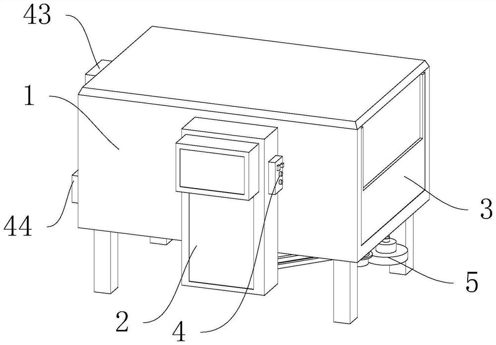
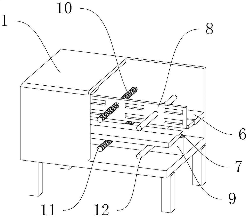
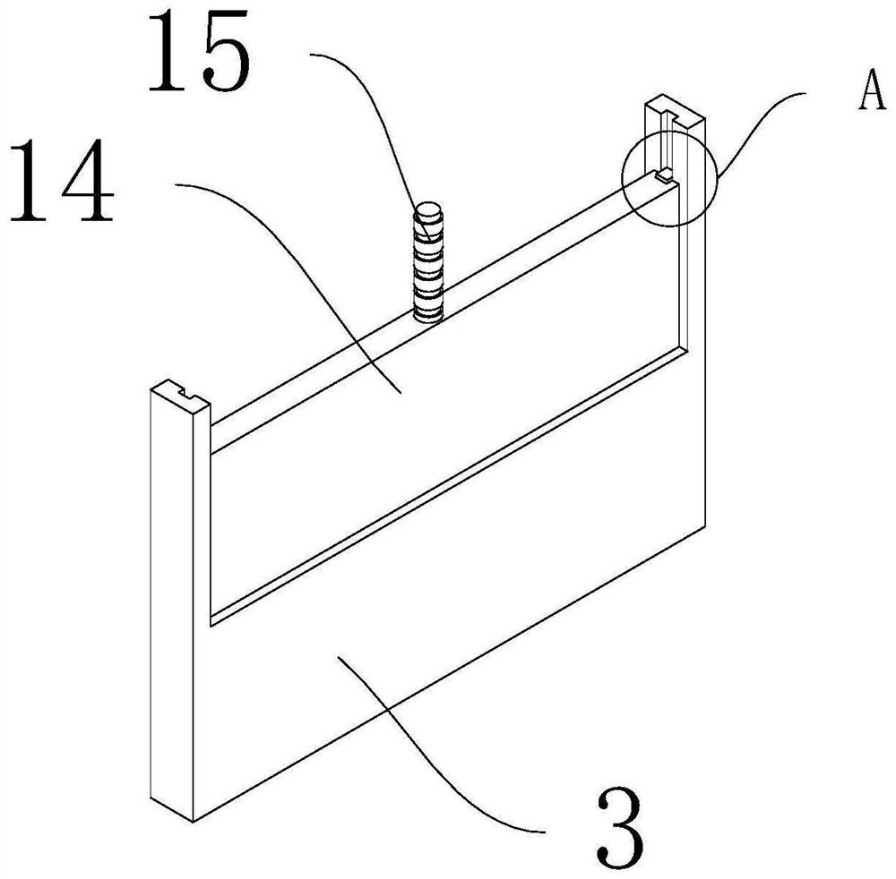
[0033] refer to Figure 1-11 , a microbial fermentation device for waste water treatment, comprising a box body 1, a feed inlet 43 and a discharge port 44 are respectively installed at the upper and lower ends of one side of the box body 1, and a first substrate 3 is installed at the bottom of one side of the box body 1, The top of the first base plate 3 is sleeved with a first telescopic plate 14, and the middle part of the first telescopic plate 14 is installed with an adjusting screw 15. One end of the adjusting screw 15 protrudes from the bottom of the first base plate 3 and a second friction wheel 5 is installed. A mounting base 13 is fixed at the joint between the top of the wheel 5 and the adjusting screw 15, and a second base plate 6 is installed between both sides of the inside of the box body 1, and the top of the second base plate 6 is clamped with a second telescopic plate 7, and the second base plate 6. A first reciprocating screw 10 and a second reciprocating scr...

Embodiment 2

[0039] refer to Figure 3-4 , as another preferred embodiment of the present invention, the difference from Embodiment 1 is that both sides of the first telescopic plate 14 are connected to the box body 1 with limiting plates 16, and both sides of the limiting plate 16 are connected to the first telescopic plate. Limiting slots 18 are opened at the joints of the plates 14, and limiting strips 17 are installed at the joints of the first expansion plate 14 both sides with the limiting plate 16, and the limiting strips 17 correspond to the positions of the limiting grooves 18, and the limiting The cross-sectional size of the position bar 17 matches the limit groove 18 .


PUM


Abstract

The invention relates to the technical field of wastewater treatment devices, particularly to a microbial fermentation device for wastewater treatment. The microbial fermentation device comprises boxbody, wherein a first substrate is mounted at the bottom of one side of the box body; the top of the first base plate is sleeved with a first telescopic plate; an adjusting screw penetrates through the middle portion of the first telescopic plate; one end of the adjusting screw extends out of the bottom of the first substrate and is provided with a second friction wheel; a second base plate is mounted between the two inner sides of the box body; a second telescopic plate is clamped at the top of the second base plate; a first reciprocating screw and a second reciprocating screw are installed on the upper side and the lower side of the second base plate correspondingly; one end of the first reciprocating screw extends out of the box body and is provided with a driving motor; a driving mechanism is installed between the driving motor and the first reciprocating screw, between the driving motor and the second reciprocating screw and between the second reciprocating screw and the second friction wheel; a first scraping plate and a second scraping plate are installed between the first reciprocating screw and the second reciprocating screw in a penetrating mode; and a disengaging mechanism is installed between the second scraping plate and the second telescopic plate.

Description

technical field [0001] The invention relates to the technical field of wastewater treatment devices, in particular to a microbial fermentation device for wastewater treatment. Background technique [0002] Wastewater treatment is the use of physical, chemical and biological methods to treat wastewater, purify wastewater, reduce pollution, and achieve the purpose of recycling and reusing wastewater and making full use of water resources. Microbial fermentation refers to the use of microorganisms under suitable conditions. Under the circumstances, the process of converting raw materials into products needed by humans through specific metabolic pathways, while the existing industrial wastewater and urban wastewater often contains rich organic matter, as well as various heavy metals, pathogenic bacteria, parasite eggs and other impurities, if Improper disposal will inevitably cause secondary pollution and seriously affect the surrounding ecological environment. Most of the exist...

Claims


Application Information

Patent Timeline
IPC IPC(8): C02F3/34
CPCC02F3/34C02F2203/006
Inventor 不公告发明人
Owner 周日艳
Why Eureka
Try Eureka