EPS line shaping equipment for engineering construction

A line and engineering technology, applied in the field of EPS line shaping equipment for engineering construction, can solve the problems of uneven mixing of aggregates, difficult drying and curing of aggregates, etc.

Inactive Publication Date: 2021-07-02
江西省龙腾实业有限公司
View PDF15 Cites 0 Cited by
  • Summary
  • Abstract
  • Description
  • Claims
  • Application Information

AI Technical Summary

Problems solved by technology

[0004] In order to overcome the shortcomings of uneven mixing of aggregates and difficult drying and curing of aggregates, the technical problem is to provide an EPS line shaping equipment for engineering construction that can stir aggregates evenly and quickly solidify aggregates

Method used


Image

  • EPS line shaping equipment for engineering construction
  • EPS line shaping equipment for engineering construction
  • EPS line shaping equipment for engineering construction

Examples


Embodiment 1

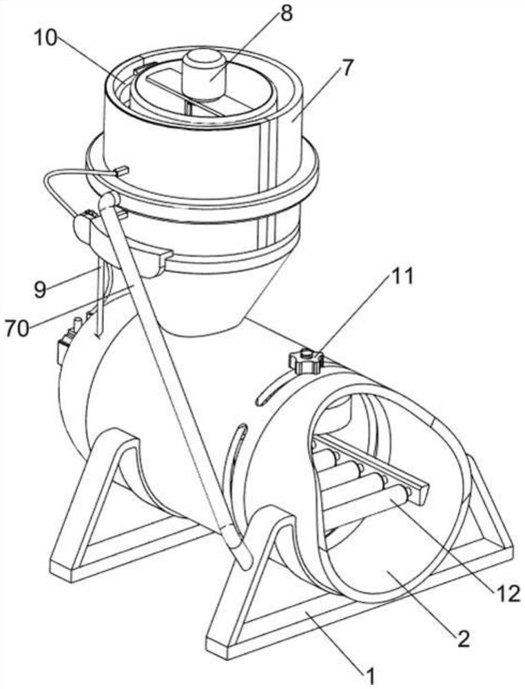
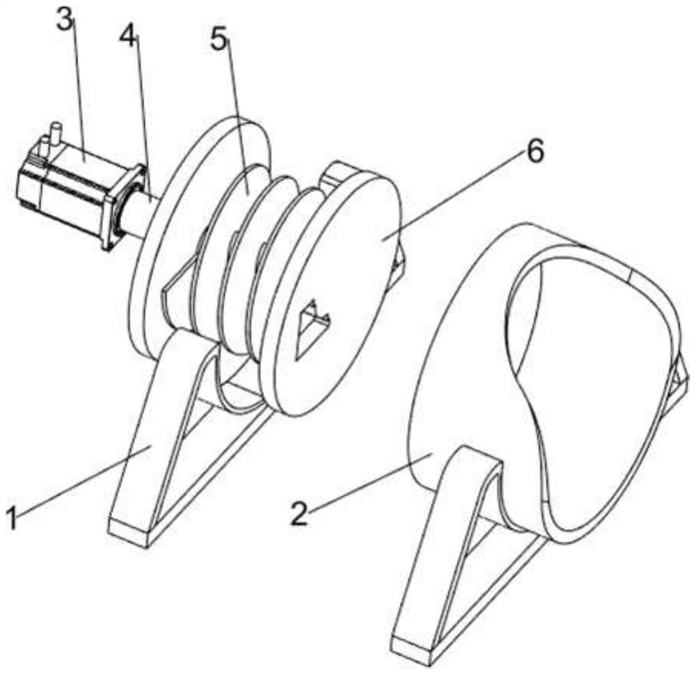
[0064] A kind of EPS line shaping equipment for engineering construction, such as Figure 1-2 As shown, it includes a first support frame 1, a connecting barrel 2, a servo motor 3, a first rotating shaft 4, a first feeding worm 5, a model plate 6, a storage mechanism 7 and a stirring mechanism 8, and two first support frames 1 There is a connecting barrel 2 between the tops, a servo motor 3 is arranged on the rear side of the connecting barrel 2, the servo motor 3 passes through the rear side of the connecting barrel 2, the output end of the servo motor 3 is provided with a first rotating shaft 4, and the first rotating shaft 4 is A first feeding worm 5 is provided, a mold plate 6 is arranged inside the connecting barrel 2, a material storage mechanism 7 is arranged on the rear side of the top of the connecting barrel 2, and a stirring mechanism 8 is arranged in the material storage mechanism 7.

[0065] The staff puts the aggregate in the material storage mechanism 7, and the...

Embodiment 2

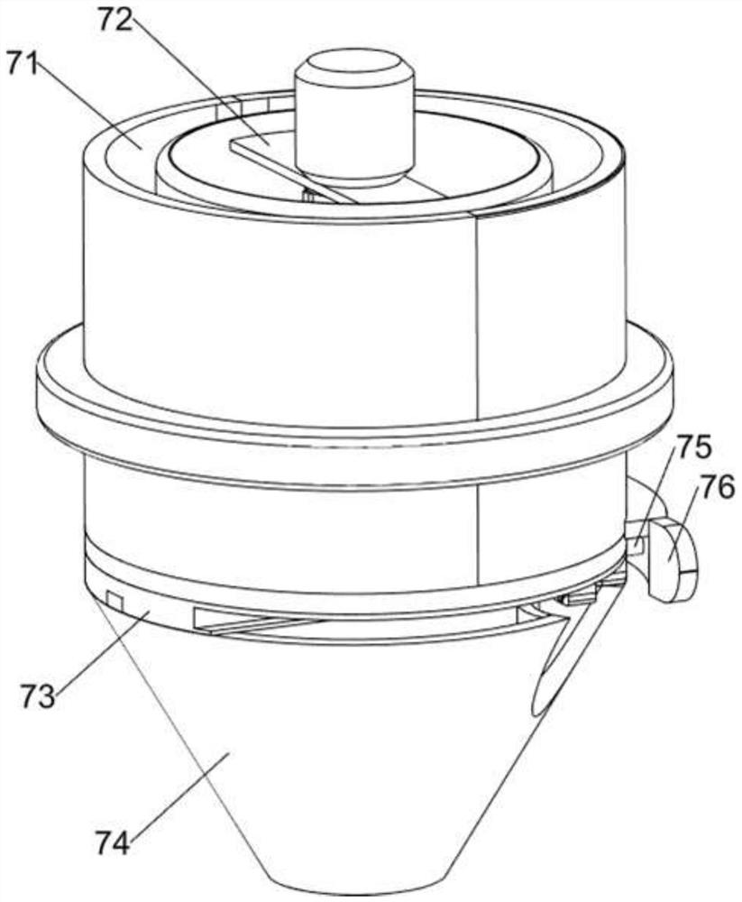
[0067] On the basis of Example 1, such as Figure 3-6 As shown, the material storage mechanism 7 includes a second support frame 70, a material storage bucket 71, a support plate 72, a baffle plate 73, a material receiving bucket 74, a guide rod 75 and a first connecting plate 76, and the first support frame on the front side 1 is provided with a second support frame 70, the second support frame 70 is provided with a storage tank 71, the storage tank 71 is provided with a support plate 72, the rear side of the top of the connecting bucket 2 is provided with a receiving bucket 74, and the connecting bucket 2 A first connecting plate 76 is arranged in the middle of the left side, and two guide rods 75 are arranged on the first connecting plate 76 , and a baffle plate 73 is slidably arranged between the guide rods 75 .

[0068] Stirring mechanism 8 includes torque motor 80, the second rotating shaft 81, the first stirring rod 82, the second stirring rod 83 and the second feeding ...

Embodiment 3

[0071] On the basis of Example 2, such as Figure 6-10 As shown, an opening and closing mechanism 9 is also included, and the opening and closing mechanism 9 includes a limit plate 90, a twist shaft 91, a third rotating shaft 92, a first bevel gear assembly 93, a fourth rotating shaft 94, a pulley assembly 95 and a second bevel gear Component 96, a limiting plate 90 is provided on the material receiving barrel 74, and a twist shaft 91 is arranged in rotation between the limiting plate 90 and the first connecting plate 76, and the baffle plate 73 is matched with the twist shaft 91, and the left rear of the top of the connecting barrel 2 The side rotation type is provided with a third shaft 92, and the twist shaft 91 and the second shaft 81 are provided with a first bevel gear assembly 93. The first bevel gear assembly 93 is composed of two bevel gears, and the bevel gears are respectively connected to the twist shaft 91 and the second shaft 81. On the second rotating shaft 81, ...


PUM


Abstract

The invention relates to shaping equipment, in particular to EPS line shaping equipment for engineering construction. The EPS line shaping equipment for engineering construction can uniformly stir aggregate and rapidly solidify the aggregate. The EPS line shaping equipment for engineering construction comprises a connecting barrel, a servo motor, a first rotating shaft, a first feeding worm, a model plate and a storage mechanism. The connecting barrel is arranged between the tops of two first supporting frames. The servo motor is arranged on one side of the connecting barrel, and the servo motor penetrates through the connecting barrel. The first rotating shaft is arranged at the output end of the servo motor. The first feeding worm is arranged on the first rotating shaft. The model plate is arranged in the connecting barrel. The storage mechanism is arranged on one side of the top of the connecting barrel. Through cooperation of the servo motor, a baffle and an opening and closing mechanism, the servo motor drives the opening and closing mechanism to work, the opening and closing mechanism controls the baffle to move left and right, and therefore aggregate is intermittently discharged while being stirred.

Description

technical field [0001] The invention relates to a sizing device, in particular to an EPS line sizing device for engineering construction. Background technique [0002] With the development of the economy and the improvement of people's living standards, the society has higher and higher requirements for aesthetic sense, and the performance of the construction industry is particularly prominent. At present, there is a kind of EPS decorative line on the market. EPS decorative line is a new type of exterior wall decorative line and component, which is more suitable for installation. It is easy to install, economical and durable on the external wall EPS and XPS insulation walls. Long and other advantages, can fire and will not emit toxic substances, is an environmentally friendly high-quality decorative building materials products. In terms of general EPS line processing, there will be some difficulties in several links such as stirring, EPS line storage, and drying. During th...

Claims


Application Information

Patent Timeline
Patent Type & Authority Applications(China)
IPC IPC(8): B29B7/44B29B7/58B29B7/60B29B7/82
CPCB29B7/82B29B7/44B29B7/60B29B7/582
Inventor 刘红霞
Owner 江西省龙腾实业有限公司
Why Eureka
Try Eureka