Municipal sludge dewatering and recycling device

An urban sludge and sludge technology, which is applied in water/sludge/sewage treatment, sludge treatment, chemical instruments and methods, etc., can solve the problem of inconvenient removal of sludge, and achieve the advantages of convenient use of equipment and prevention of solidification. Effect

Inactive Publication Date: 2020-12-01
高超
View PDF7 Cites 6 Cited by
  • Summary
  • Abstract
  • Description
  • Claims
  • Application Information

AI Technical Summary

Problems solved by technology

[0005] In order to overcome the shortcomings of the current municipal sludge dehydration method that the dehydrated sludge is inconvenient to take out and the sludge needs to be continuously poured into the feed port for dehydration, the technical problem of the present invention is: to provide a dehydrated sludge that can be conveniently dehydrated. A municipal sludge dehydration recycling device that takes out sludge and can automatically add sludge for dehydration

Method used


Image

  • Municipal sludge dewatering and recycling device
  • Municipal sludge dewatering and recycling device
  • Municipal sludge dewatering and recycling device

Examples


Embodiment 1

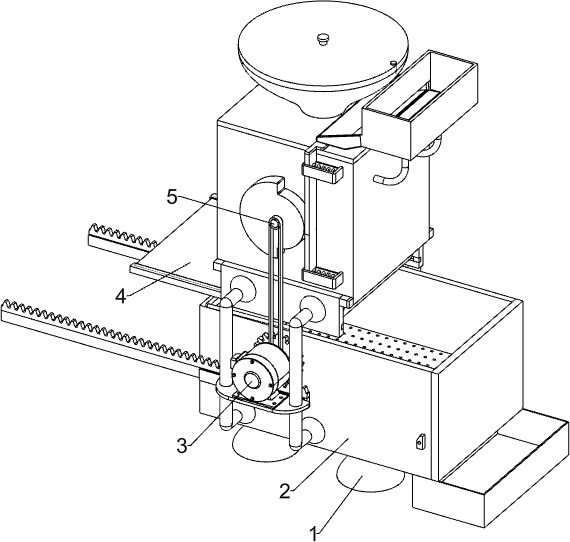
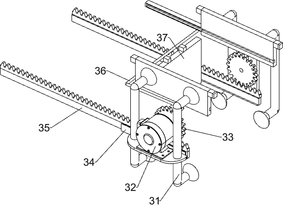
[0023] A kind of urban sludge dehydration recycling device, such as Figure 1-5 As shown, it includes a bracket 1, a dehydration container 2, an extruding assembly 3 and a discharge assembly 4. A dehydration container 2 for sludge dehydration is installed on the top of the bracket 1, and an extruder for dehydration by extrusion is installed on the dehydration container 2. Press assembly 3, and the top of extrusion assembly 3 is equipped with a discharge assembly 4 for discharging sludge by sliding.

[0024] When it is necessary to use the device for sludge dehydration, first the sludge is poured into the discharge assembly 4, and the sludge enters the dehydration container 2 through the discharge assembly 4, and then the extrusion assembly 3 is controlled to start working, and the dehydration container 2 The sludge inside is dehydrated. At the same time, when the extrusion component 3 dehydrates the sludge, it will trigger the discharge component 4 to stop the sludge from fall...

Embodiment 2

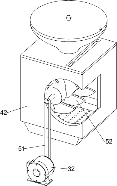
[0032] On the basis of Example 1, such as figure 1 , 6 Shown in and 7, it also includes a stirring assembly 5, the stirring assembly 5 for sludge stirring is installed in the material storage frame 42 by rotating, the stirring assembly 5 includes a transmission pulley group 51 and a stirring blade 52, and in the material storage frame 42 The central rotating type is provided with stirring blades 52 , and a transmission pulley set 51 is connected between the front end of the stirring blades 52 and the output shaft of the reduction motor 32 .

[0033] When the reduction motor 32 rotates, the transmission pulley set 51 drives the stirring blade 52 to rotate, and then the sludge is stirred, so that the sludge can be prevented from solidifying.

[0034] Also includes a blanking assembly 6, the material storage frame 42 top right side is installed with a blanking assembly 6 for blanking by sliding, the blanking assembly 6 includes a cam 61, a push plate 62, a second spring 63, and ...


PUM


Abstract

The invention relates to a recycling device, in particular to a municipal sludge dewatering and recycling device. According to the municipal sludge dewatering and recycling device, dewatered sludge can be conveniently taken out, and sludge can be automatically added for dewatering. The municipal sludge dewatering and recycling device comprises a bracket; a dewatering container which is arranged onthe bracket and is used for dewatering the sludge; an extrusion assembly which is arranged on the dehydration container and is used for dehydrating in an extrusion manner; and a discharging assemblywhich is mounted on the extrusion assembly and used for discharging the sludge in a sliding manner. With cooperation of the dewatering container and the extrusion assembly, sludge can be dewatered, meanwhile, dewatered sludge can be automatically discharged, the equipment is very convenient to use; with application of the discharging assembly, when the sludge is dewatered, falling of the sludge can be stopped, and after the sludge is dewatered, the sludge can be automatically discharged.

Description

technical field [0001] The invention relates to a recycling device, in particular to a municipal sludge dehydration recycling device. Background technique [0002] Sludge generated during urban life and the operation and maintenance of urban municipal facilities related to urban life activities. According to the source, it can be divided into sewage plant sludge, water supply plant sludge, drainage pipe sludge, dredging sludge and construction mud. The properties of sludge from different sources are very different, and the corresponding treatment and disposal technical requirements and resource utilization methods are also different. Sludge can be recycled, so it needs to be dewatered. [0003] The patent application publication number is CN109721218A, which discloses a sludge dehydration treatment device for urban sewage, including a shell, a feed inlet, a drug inlet, a mixing box, a discharge outlet, a conveying box, a motor Wheel, secondary driving wheel, belt output s...

Claims


Application Information

Patent Timeline
Patent Type & Authority Applications(China)
IPC IPC(8): C02F11/121
CPCC02F11/121
Inventor 高超
Owner 高超
Why Eureka
Try Eureka