
Component for fabricated building and fabricated building with same

A prefabricated and architectural technology, which is applied to the on-site preparation of building components, building structure, and construction, etc., can solve the problems of high construction difficulty and low construction efficiency, and achieve the advantages of low construction difficulty, convenient construction and reliable connection. Effect

Pending Publication Date: 2020-12-01
CHINA CONSTR SCI & IND CORP LTD
View PDF0 Cites 0 Cited by
  • Summary
  • Abstract
  • Description
  • Claims
  • Application Information

AI Technical Summary

Problems solved by technology

[0005] Therefore, the technical problem to be solved by the present invention is to overcome the construction method of electromechanical pipelines in the prior art. In order to bypass the steel structure, it is necessary to bend the electromechanical pipelines. The construction is difficult, resulting in low construction efficiency, thereby providing A prefabricated building component

Method used


Image

  • Component for fabricated building and fabricated building with same
  • Component for fabricated building and fabricated building with same
  • Component for fabricated building and fabricated building with same

Examples


Embodiment 1

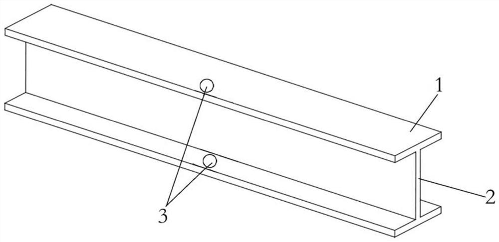
[0034] The prefabricated components provided in this embodiment, such as figure 1 As shown, there is a horizontal plate 1 arranged horizontally and a vertical plate 2 arranged vertically; the horizontal plate 1 has two pieces, which are arranged above and below the vertical plate 2 at intervals; the steel member of this embodiment is H-shaped steel, and the Each of the horizontal plates 1 has a pipeline hole 3 that penetrates up and down, wherein the pipeline hole 3 on the upper horizontal plate 1 and the pipeline hole 3 on the lower horizontal plate 1 are arranged oppositely; the electromechanical pipeline 7 can be directly connected from the pipeline hole 3 through;

[0035] A pipeline hole 3 is set on the horizontal plate 1 of the H-shaped steel. The setting of the pipeline hole 3 prevents the electromechanical pipeline 7 from turning over at the steel member when it is laid vertically along the wall, which reduces the construction difficulty; improves the construction of t...

Embodiment 2

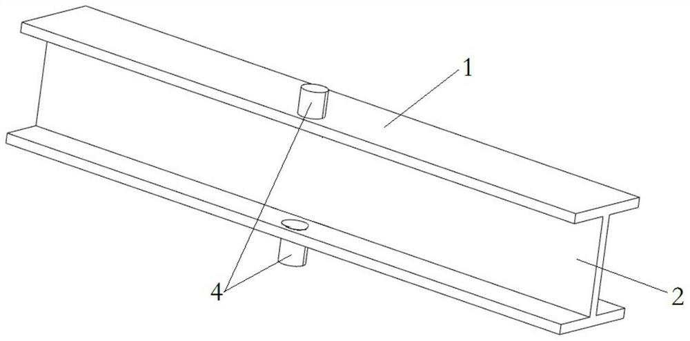
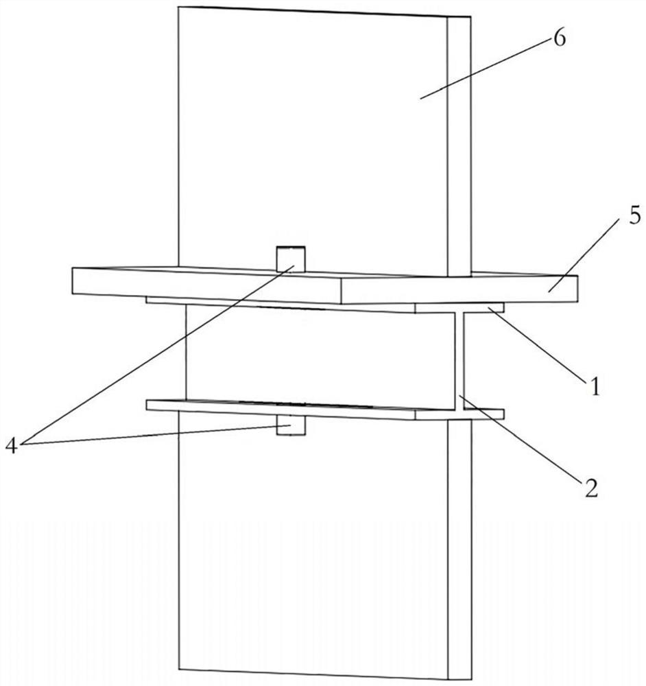
[0039] The prefabricated building provided in this embodiment includes the component for the prefabricated building described in Embodiment 1; this embodiment uses H-shaped steel as the component for the prefabricated building; image 3 As shown, casings 4 are arranged in the pipeline holes 3 of the H-shaped steel, and a structural floor 5 is horizontally erected above the H-shaped steel. equal to 5 cm, preferably 5 cm.

[0040] like Figure 4 As shown, a wall panel 6 is arranged above the structural floor 5 and below the H-shaped steel, and the H-shaped steel is used as a beam to connect the wall panel 6 and the structural floor 5 or connect the wall panel 6 and the wall panel 6;

[0041] like Figure 5 As shown, the electromechanical pipeline 7 is laid along the vertical direction of the wallboard 6. When the electromechanical pipeline 7 passes through the H-shaped steel, the electromechanical pipeline 7 passes through the pipeline hole 3 of the H-shaped steel, effectively...


PUM


Abstract

The invention provides a component for a fabricated building and the fabricated building with the component, and belongs to the technical field of fabricated buildings. The component for the fabricated building is provided with a transverse plate which is transversely arranged, and a pipeline hole which is through up and down is formed in the transverse plate. According to the component for the fabricated building, when an electromechanical pipeline is constructed along a wallboard and encounters a steel component, the electromechanical pipeline penetrates into the pipeline hole, the electromechanical pipeline can penetrate through the steel component, the steel component does not need to be wound, the construction difficulty is low, and the constructed structure is more attractive. The construction efficiency is improved, the length of the electromechanical pipeline is reduced, and labor and material cost is saved.

Description

technical field [0001] The invention relates to the technical field of prefabricated buildings, in particular to a component for a prefabricated building and a prefabricated building with the same. Background technique [0002] The prefabricated building refers to the transfer of a large number of on-site operations in the traditional construction method to the factory. The prefabricated concrete structure and steel structure for the building are processed and manufactured in the factory, and transported to the construction site. The prefabricated concrete structure is passed through The steel structure is assembled and installed on site to form a building. [0003] After the main body construction is completed, the multi-disciplinary sub-project construction will be carried out. When the electromechanical pipeline is installed along the prefabricated concrete structure, when encountering steel components, in the prior art, the electromechanical pipeline is bent to one side...

Claims


Application Information

Patent Timeline
Patent Type & Authority Applications(China)
IPC IPC(8): E04C3/06E04G15/06H02G3/22
CPCE04C3/06E04G15/06H02G3/22
Inventor 张鹏飞李旺杨坤郭发强王恒张永明孙元鑫
Owner CHINA CONSTR SCI & IND CORP LTD
Learn More