
Rotary drying device for seed storage

A rotary drying and seeding technology, which is applied in the agricultural field, can solve the problems of water vapor cannot be quickly discharged, hot air seeds are difficult, and the drying time is long, so as to achieve the effects of uniform and thorough drying, shortening the drying time, and improving the drying time

Inactive Publication Date: 2020-12-01
王莹莹
View PDF0 Cites 3 Cited by
  • Summary
  • Abstract
  • Description
  • Claims
  • Application Information

AI Technical Summary

Problems solved by technology

[0003] The existing grain seed drying device is to move the grain seeds through the stirring mechanism and contact with the incoming hot air, but it is difficult for the hot air to enter the inside of the piled seeds, and the water vapor generated by evaporation cannot be discharged quickly, so When drying, it needs a long time of agitation to make the grain contact with hot air, and the drying time is long, so as to avoid the reduction of efficiency. Therefore, it is necessary to improve the existing drying device to solve the above problems.

Method used


Image

  • Rotary drying device for seed storage
  • Rotary drying device for seed storage
  • Rotary drying device for seed storage

Examples


Embodiment 1

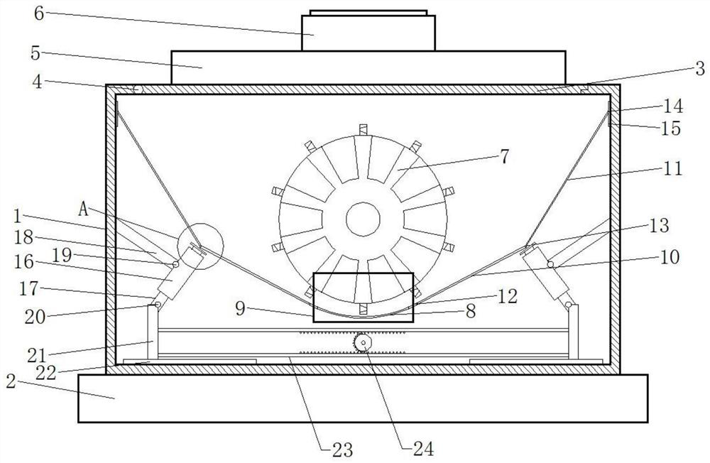
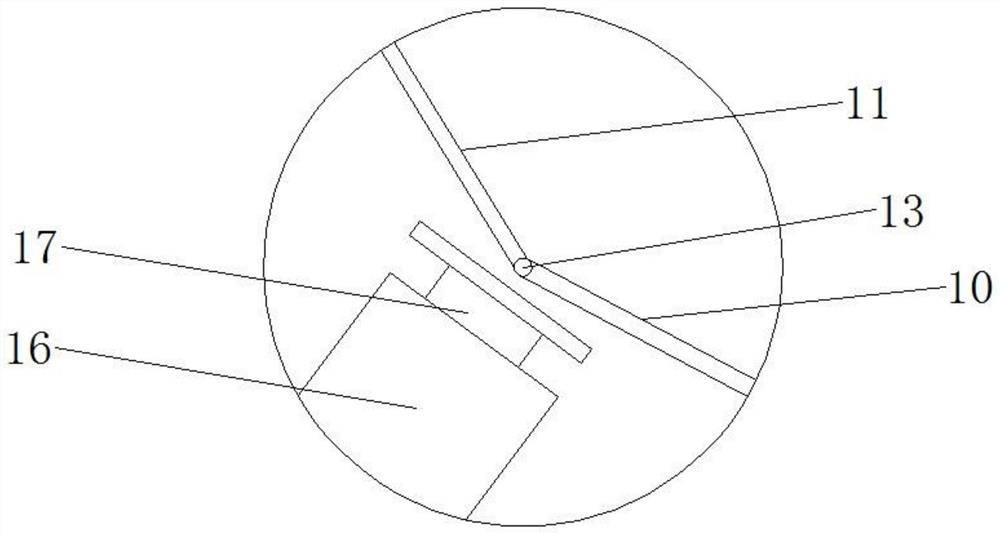
[0020] Please refer to the figure, in the embodiment of the present invention, a rotary drying device for seed storage includes a box body 1, a base 2, a sealing cover 3, a hinge 4, a heating box 5 and a fan 6; the box body 1 is fixedly installed on On the base 2, a sealing cover 3 is arranged on the top of the box body 1, and the sealing cover 3 is connected to the box body 1 through a hinge 4, so that the sealing cover 3 can be opened outwards, and the grain seeds are packed into the box body 1 Inside: a heating box 5 is fixedly installed on the outer surface of the sealing cover 3, and several blowing holes extending to the lower surface of the sealing cover 3 are provided on the heating box 5, and the hot air in the heating box 5 is sent into the box body 1 Inside, a heating element is installed in the heating box 5 to heat the air entering the interior and provide hot air for drying. A fan 6 is installed on the top of the heating box 5, and the fan 6 sends the external air...

Embodiment 2

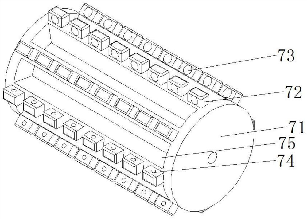
[0023] On the basis of Embodiment 1, the rotating roller 7 includes a rotating roller 71 with a cylindrical structure, and several toggle blocks 72 are fixedly installed on the side wall of the rotating roller 71, and the toggle block 72 is a rectangular block structure. The toggle block 72 is provided with a feed port 73 facing the direction of rotation and a discharge port 74 on the other side, and the feed port 73 communicates with the discharge port 74, and the diameter of the feed port 73 is greater than the diameter of the discharge port 74 , preferably, the diameter of the feed port 73 is 1.5-2 times the diameter of the discharge port 74, forming a cavity with a circular truncated structure, so that the grain seeds enter the interior from the feed port 73, store them inside, and pass through the opening smaller The discharge port 74 flows out downwards, so that the grain seeds follow the roller 71 and slowly fall from the shifting block 72; preferably, the shifting block...


PUM


Abstract

The invention relates to the field of agriculture, and particularly discloses a rotary drying device for seed storage. The rotary drying device comprises a box body, a base, a sealing cover, a hinge,a heating box and a fan; a horizontal rotating roller for raising cereal seeds is mounted in the box body; first swing plates are rotationally connected to the left end and the right end of a fixed bottom plate through horizontal first pin shafts correspondingly; and the other ends of the first swing plates incline upwards and are rotationally connected with second swing plates through horizontalsecond pin shafts, the other ends of the second swing plates incline upwards, sliding rods are slidably arranged in supporting sleeves in a penetrating mode, push plates perpendicular to the sliding rods are fixedly mounted at the upper ends of the sliding rods, and the push plates face the second pin shafts. Through the multiple arranged swing plates and the jacking direction of the sliding rodsswinging for extending and retracting, the swing plates are driven to move up and down, the cereal seeds falling on the swing plates are turned over, the cereal seeds make contact with hot air conveniently, the cereal seeds are pushed to move towards the rotating roller, and the seeds are raised under the action of the rotating roller.

Description

technical field [0001] The invention relates to the field of agriculture, in particular to a rotary drying device for seed storage. Background technique [0002] With the continuous advancement of agricultural technology, the output of agricultural products is gradually increasing. In the existing agricultural production, the stored grain and other agricultural products will be dried to ensure that the grain can be stored for a long time. [0003] The existing grain seed drying device is to move the grain seeds through the stirring mechanism and contact with the incoming hot air, but it is difficult for the hot air to enter the inside of the piled seeds, and the water vapor generated by evaporation cannot be discharged quickly, so When drying, it needs to stir for a long time to make the grain contact with the hot air, and the drying time is long, so that the efficiency is reduced. Therefore, it is necessary to improve the existing drying device to solve the above problems....

Claims


Application Information

Patent Timeline
Patent Type & Authority Applications(China)
IPC IPC(8): F26B11/16F26B21/00F26B25/04F26B25/10
CPCF26B11/16F26B21/001F26B25/04F26B25/10
Inventor 王莹莹
Owner 王莹莹
Learn More