Three-dimensional laser radar positioning and navigation method for intelligent inspection and inspection robot

A three-dimensional laser and radar positioning technology, applied in the field of inspection robots, can solve the problems of affecting the positioning accuracy, positioning loss, and inability to effectively describe the three-dimensional environmental space, and achieve the effect of strong anti-electromagnetic interference and improved inspection accuracy

Active Publication Date: 2020-12-01
SHANGHAI AEROSPACE SYST ENG INST
View PDF4 Cites 46 Cited by
  • Summary
  • Abstract
  • Description
  • Claims
  • Application Information

AI Technical Summary

Problems solved by technology

However, the visual sensor is easily affected by ambient light, and in some situations with strong exposure or low brightness, the positioning will be lost.
However, two-dimensional laser radar can only obtain two-dimensional information of the environment at a certain height, and cannot effectively describe the three-dimensional environmental space, which will affect the positioning accuracy.

Method used


Image

  • Three-dimensional laser radar positioning and navigation method for intelligent inspection and inspection robot
  • Three-dimensional laser radar positioning and navigation method for intelligent inspection and inspection robot
  • Three-dimensional laser radar positioning and navigation method for intelligent inspection and inspection robot

Examples


Embodiment 1

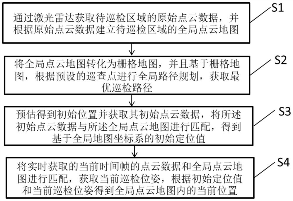
[0063] See figure 1 , The present embodiment provides a three-dimensional laser radar navigation method for intelligent data logging comprises the steps of:

[0064] S1: obtaining raw point cloud data to be inspection area by a laser radar, and the inspection zone to be build the global map based on the original point cloud point cloud data;

[0065] S2: the global point cloud map into a grid map and grid-based map, global path planning conducted according to a preset inspection points, inspection obtain optimal path;

[0066] S3: obtain an initial position estimate and acquires its initial point cloud data, the global data and the initial point cloud point cloud map matching to obtain an initial target value based on the global map coordinate system;

[0067] S4: point cloud point cloud data and a global map of the current time acquired in real time to match the frame, acquires the current pose inspection, to give the current position within the global map based on the point clou...

Embodiment 2

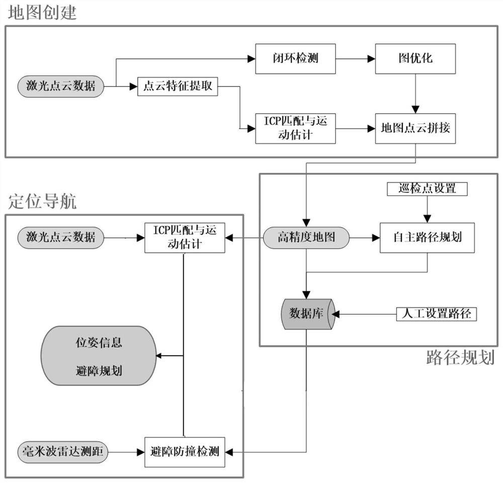
[0091] See Figure 5 An inspection robot includes:

[0092] The scanning device 1: inspection for scanning the area to be different, the raw point cloud data obtained in different regions of the inspection to be real-time data point and the current position of the millimeter-wave cloud radar data. In particular, the scanning laser radar apparatus 1 comprises a three-dimensional millimeter-wave radar 11 and 12; three-dimensional laser radar 11 for acquiring the raw point cloud data and the point cloud data in real time; three-dimensional laser radar millimeter-wave radar 12 for detecting the surrounding obstacle information, with 11 scans. Using a three-dimensional laser radar 11 to implement the present embodiment, it is possible to achieve a good three-dimensional perception of the environment, independent path planning and navigation functionality.

[0093] Map Building Blocks 2: raw point cloud data is used to extract features optimized to obtain point cloud data, the point clou...


PUM


Abstract

The invention discloses a three-dimensional laser radar positioning and navigation method for intelligent inspection. The method comprises the steps of S1 acquiring original point cloud data of a to-be-inspected area through a laser radar, and establishing a global point cloud map; S2 converting the global point cloud map into a grid map, and performing global path planning according to preset patrol points to obtain an optimal patrol path; S3 estimating to obtain an initial position, obtaining initial point cloud data of the initial position, and matching the initial point cloud data with theglobal point cloud map to obtain an initial positioning value based on a global map coordinate system; and S4 through matching of the current frame point cloud data obtained in real time and the global point cloud map, obtaining a current inspection pose. As the method is realized by utilizing the three-dimensional laser radar, the functions of three-dimensional perception, autonomous path planning and positioning navigation of the environment can be well realized, and the inspection precision of the inspection robot is improved; GPS positioning navigation does not need to be adopted, and theanti-electromagnetic interference capacity is high.

Description

Technical field [0001] The present invention is in the inspection robot, and more particularly relates to a three-dimensional laser radar positioning and navigation intelligence inspection method and inspection robot. Background technique [0002] With advances in technology, inspection robot to play in industrial, military, daily life in the increasingly important role, instead of doing so to complete the park security, special high-risk work scene inspection, field investigation and other tasks. To complete the inspection of independent security and other tasks, is the basis for high-precision positioning and navigation. [0003] Currently, the prior art, inspection robot navigation positioning is divided into rail and non-rail type. There rail includes a magnetic suspension rail and rail navigation, positioning accuracy of these two methods, but needs to lay tracks in advance, difficult transformation patrol routes, poor flexibility. Without rail positioning navigation way you...

Claims


Application Information

Patent Timeline
Patent Type & Authority Applications(China)
IPC IPC(8): G01S17/89G01S13/93
CPCG01S17/89G01S13/93Y02T10/40
Inventor 闫雪娇谷鹏程陈萌邵济明蒋松陈伟堤
Owner SHANGHAI AEROSPACE SYST ENG INST
Why Eureka
Try Eureka