
Permanent magnet motor harmonic current prediction method

A permanent magnet motor, harmonic current technology, applied in special data processing applications, complex mathematical operations, design optimization/simulation, etc., can solve the problems of slow calculation speed, fast calculation speed, tens of hours, etc.

Active Publication Date: 2020-12-01
ZHEJIANG UNIV +1
View PDF7 Cites 4 Cited by
  • Summary
  • Abstract
  • Description
  • Claims
  • Application Information

AI Technical Summary

Problems solved by technology

Based on the finite element method, a co-simulation model including the motor and the inverter can be established to analyze the harmonic current of the motor. The calculation accuracy is high and the application range is wide, but the calculation speed is slow and usually takes dozens of hours.
Analytical method (typically such as paper W.Liang, J.Wang and W.Fang, "Analytical Modeling of Sideband Current Harmonic Components in Induction Machine Drive With Voltage Source Inverter by an SVM Technique," inIEEE Transactions on Power Electronics, vol.28, no. 11, pp.5372-5379, Nov.2013.) Based on a specific modulation strategy (such as space vector modulation), the harmonic current expression of a certain type of specific motor is directly derived, and the calculation speed is fast but the scope of application is narrow
Moreover, the derivation of the analytical method is based on a lumped parameter model of a certain type of specific motor, and it is difficult to accurately consider the influence of the saturation effect of the ferromagnetic material inside the motor on the harmonic current calculation.

Method used


Image

  • Permanent magnet motor harmonic current prediction method
  • Permanent magnet motor harmonic current prediction method
  • Permanent magnet motor harmonic current prediction method

Examples


Embodiment Construction

[0057] The present invention will be further described below in conjunction with the accompanying drawings and implementation examples, so that the advantages and features of the present invention can be more easily understood by those skilled in the art, so as to define the protection scope of the present invention more clearly.

[0058] Such as figure 1 Shown, embodiment of the present invention is as follows:

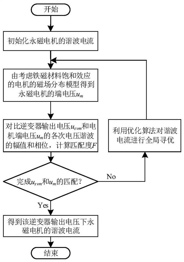
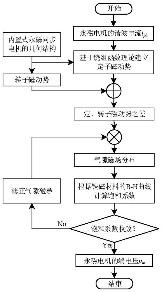
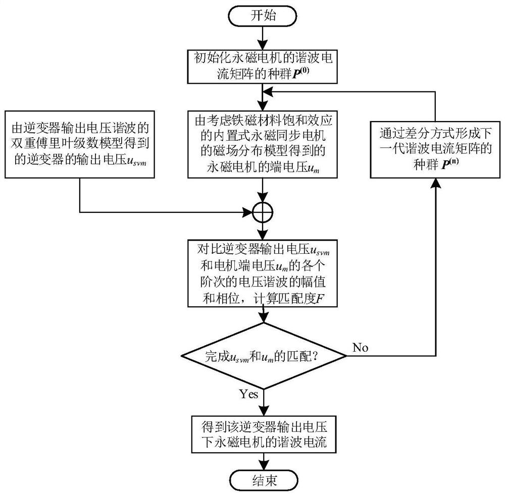
[0059] Input the initial harmonic current into the magnetic field distribution model of the motor considering the saturation effect of ferromagnetic materials to obtain the terminal voltage u of the permanent magnet motor m , with the terminal voltage u of the permanent magnet motor m and inverter output voltage u svm The matching degree is the optimization goal, and the harmonic current of each order input by the magnetic field distribution model of the motor is globally optimized through the optimization algorithm. When the terminal voltage of the permanent mag...


PUM


Abstract

The invention discloses a prediction method for harmonic current of a permanent magnet motor. A motor magnetic field distribution model considering the ferromagnetic material saturation effect is established, the input of the motor magnetic field distribution model is the harmonic current of the permanent magnet motor, and the output is the terminal voltage of the permanent magnet motor; establishing a double Fourier series model of inverter output voltage harmonics based on space vector modulation of a modulation function, and inputting the modulation depth to obtain the output voltage of theinverter; establishing a matching degree between the terminal voltage of the permanent magnet motor and the output voltage of the inverter and taking the matching degree as an optimization target; and proposing a harmonic current matching method, i.e., carrying out global optimization on each order of harmonic current of the motor magnetic field distribution model through an optimization algorithm, and solving to obtain the amplitude and phase of each order of harmonic current so as to obtain the harmonic current. The time for processing the harmonic current is shorter than that of a finite element processing mode, and an output result is consistent and accurate with a result calculated by a finite element.

Description

technical field [0001] The invention relates to a parameter detection method of a permanent magnet motor in the field of motor electromagnetic performance analysis, in particular to a prediction method of a harmonic current of a permanent magnet motor. Background technique [0002] Accurate and rapid analysis of the electromagnetic performance of motors is the basis for the design of high-performance permanent magnet motors. High-performance permanent magnet motors are generally driven by voltage source inverters based on pulse width modulation, but the inherent switching process of the inverter will generate rich magnetic field time harmonics in the motor, and the resulting harmonic current will have a negative impact on the motor. Performance brings a series of damages, such as increase in torque ripple, electromagnetic loss, noise, and vibration. [0003] At present, the finite element method and analytical method are generally used to analyze the harmonic current of the...

Claims


Application Information

Patent Timeline
IPC IPC(8): G06F30/20G06F17/10
CPCG06F17/10G06F30/20
Inventor 黄晓艳陈卓李赵凯俞东史婷娜阎彦
Owner ZHEJIANG UNIV
Learn More