
Permanent magnet synchronous motor flux linkage harmonic observation and torque ripple suppression method

A permanent magnet synchronous motor and torque ripple technology, which is applied in the direction of motor generator control, electronic commutation motor control, control generator, etc. Problems such as torque ripple and insufficient continuity

Active Publication Date: 2020-12-01
HEFEI UNIV OF TECH
View PDF4 Cites 6 Cited by
  • Summary
  • Abstract
  • Description
  • Claims
  • Application Information

AI Technical Summary

Problems solved by technology

[0009] 1. For the torque ripple suppression of the permanent magnet synchronous motor drive system, the schemes reported in the literature usually need to build an accurate torque ripple model isomorphically, and calculate the harmonic current that needs to be compensated according to the model to generate additional torque ripple Suppress the electromagnetic torque ripple of the permanent magnet synchronous motor itself. Therefore, the harmonic compensation current calculated by this scheme when the parameters of the permanent magnet synchronous motor are inaccurate cannot effectively suppress the torque ripple;
[0010] 2. The existing methods often only focus on improving the tracking performance of the current loop and the speed loop to achieve the purpose of smooth output of the speed, and have not effectively suppressed the electromagnetic torque ripple inside the permanent magnet synchronous motor;
[0011] 3. When the existing methods are faced with inaccurate parameters of permanent magnet synchronous motors, the solutions usually require a lot of calculations or the continuity of control is not enough

Method used


Image

  • Permanent magnet synchronous motor flux linkage harmonic observation and torque ripple suppression method
  • Permanent magnet synchronous motor flux linkage harmonic observation and torque ripple suppression method
  • Permanent magnet synchronous motor flux linkage harmonic observation and torque ripple suppression method

Examples


Embodiment Construction

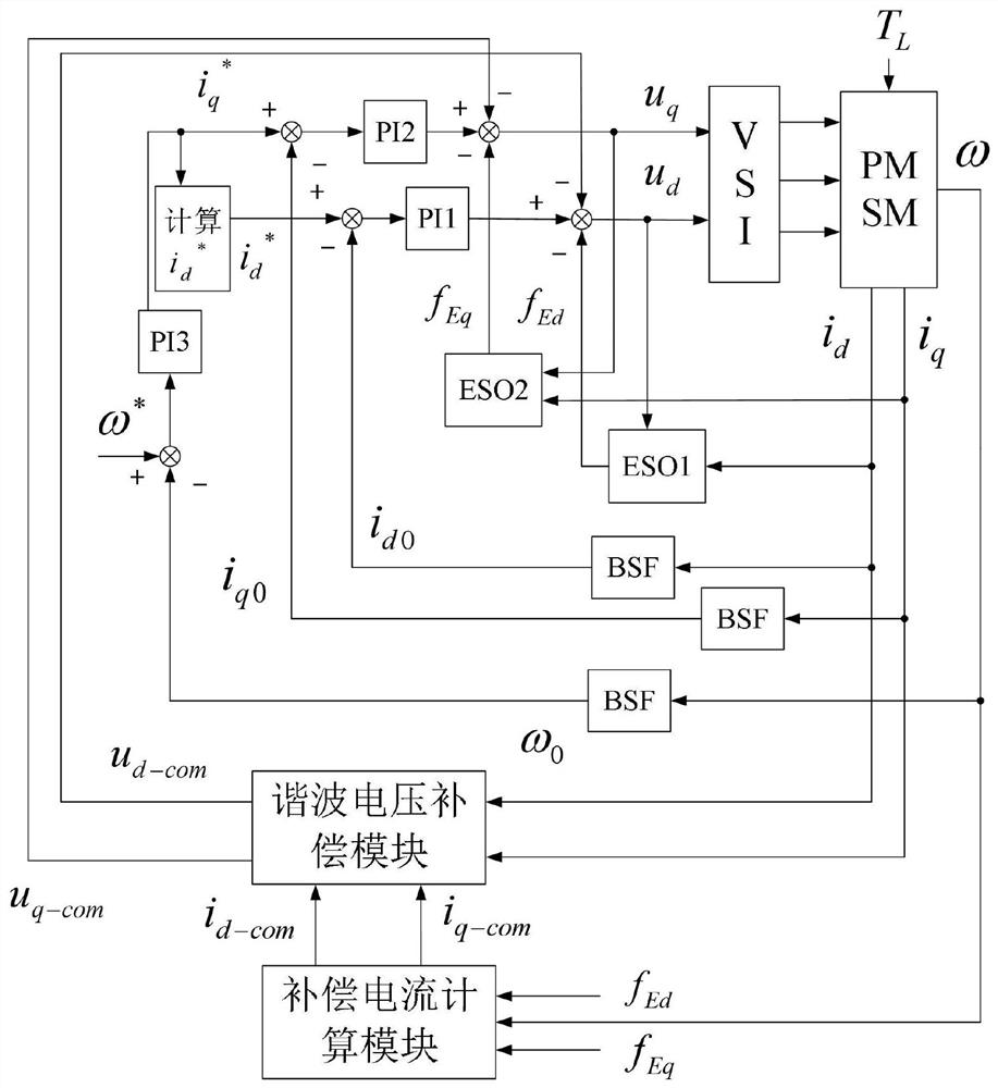
[0116] figure 1 It is the flux linkage harmonic observation and torque ripple suppression control diagram of the permanent magnet synchronous motor in the present invention.

[0117] figure 1 The VSI in is a three-phase voltage source inverter, and the PMSM is a permanent magnet synchronous motor. The parameters involved in this embodiment include: a given electrical angular velocity ω * =500rad / s, given load torque T L =15N.m, given 6 times electrical angular velocity pulsation amplitude ω 6 * =0, the transfer function of the proportional-integral regulator PI1 is Among them, the proportional coefficient K of the proportional-integral regulator PI1 P1 2000, the integral coefficient K of the proportional integral regulator PI1 I1 is 70000; the transfer function of the proportional-integral regulator PI2 is Among them, the proportional coefficient K of the proportional-integral regulator PI2 P2 2000, integral coefficient K of proportional integral regulator PI2 I2 i...


PUM


Abstract

The invention discloses a permanent magnet synchronous motor flux linkage harmonic observation and torque ripple suppression method, and relates to the field of new energy automobile permanent magnetsynchronous motor driving. Counter electromotive force harmonics fEd and fEq are observed in real time through an extended state observer, and counter electromotive force harmonic compensation is performed on an input end, so that the output current of a permanent magnet synchronous motor is enabled to have no harmonic, and interference of the harmonic current to a control system can be avoided. And meanwhile, harmonic compensation current is calculated according to the observed back electromotive force harmonics fEd and fEq, and is matched with output current of the permanent magnet synchronous motor to obtain harmonic compensation voltage. A simulation result shows that the flux linkage harmonic observation and torque ripple suppression method designed by the invention is effective. Compared with other torque ripple suppression strategies, the method has the advantage that the torque ripple of the permanent magnet synchronous motor can be effectively suppressed on the premise of notadditionally arranging extra hardware facilities and not needing to construct an accurate torque ripple model and complex harmonic compensation current calculation.

Description

technical field [0001] The invention relates to the drive field of permanent magnet synchronous motors for new energy vehicles, in particular to a method for observing flux harmonics of permanent magnet synchronous motors and suppressing torque ripple. Background technique [0002] In the process of design and manufacture, due to the influence of the rotor pole structure of the permanent magnet synchronous motor, the ideal sine wave cannot be achieved, resulting in a large number of high-order harmonics in the motor flux linkage. These factors are reflected on the permanent magnet synchronous motor, which will make the electromagnetic torque output by the permanent magnet synchronous motor pulsate. [0003] On the one hand, torque pulsation will generate electromagnetic noise, reduce the control performance of the drive system, and cause speed fluctuations during the operation of the permanent magnet synchronous motor; on the other hand, in some vehicle operating conditions,...

Claims


Application Information

Patent Timeline
IPC IPC(8): H02P21/05H02P21/22H02P21/13H02P6/182
CPCH02P6/182H02P21/05H02P21/13H02P21/22
Inventor 杨淑英储昭晗谢震马铭遥张兴
Owner HEFEI UNIV OF TECH
Learn More