
Left auricle occluder and using method thereof

An occluder and fixing element technology, applied in the field of medical devices, can solve the problems of endangering the health of patients, unable to function normally, easy to produce blood clots, etc., and achieve the effect of flexible use

Active Publication Date: 2020-12-04
上海介入医疗器械有限公司 +1
View PDF5 Cites 5 Cited by
  • Summary
  • Abstract
  • Description
  • Claims
  • Application Information

AI Technical Summary

Problems solved by technology

However, the shape of the human left atrial appendage is various, and the internal structure of the left atrial appendage is relatively complex. Clinical experience has proved that after using the existing left atrial appendage occluder to occlude the left atrial appendage, the common problems are as follows: (1) Using a plug-type occluder After occlusion, a residual cavity is likely to be left near the left atrial appendage, and thrombus is still prone to occur in this residual cavity, which endangers the health of the patient; (2) After occlusion with a double-disc occluder, if the fixation device is normal, The sealing device may affect human tissues near the atrial appendage, such as valves, otherwise the fixing device cannot function normally
The above problems are mostly caused by the inability of the existing device settings to better match with many left atrial appendage tissues. In order to solve the above problems, it is urgent to invent a new left atrial appendage occluder, which can Select and match the occlusion device, improve the adaptability of the left atrial appendage occluder to various forms of left atrial appendage, further expand the scope of application of percutaneous left atrial appendage occlusion surgery, and benefit more patients

Method used


Image

  • Left auricle occluder and using method thereof
  • Left auricle occluder and using method thereof
  • Left auricle occluder and using method thereof

Examples


Embodiment 1

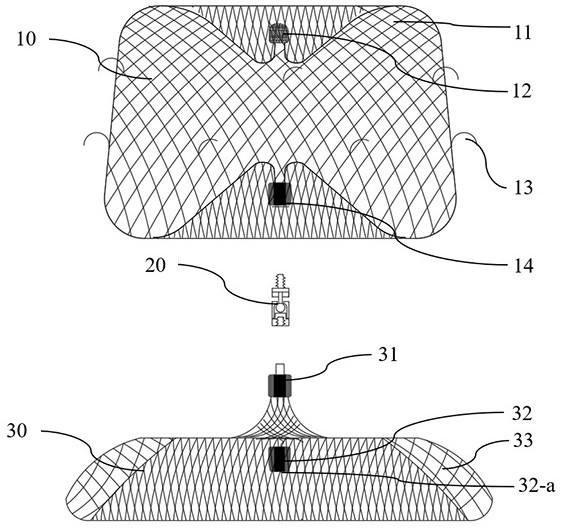
[0094] Such as figure 1 and Figure 7 As shown, it is a left atrial appendage occluder, including an anchoring part 10, a connecting part 20 and a covering part 30 sequentially connected in the axial direction.

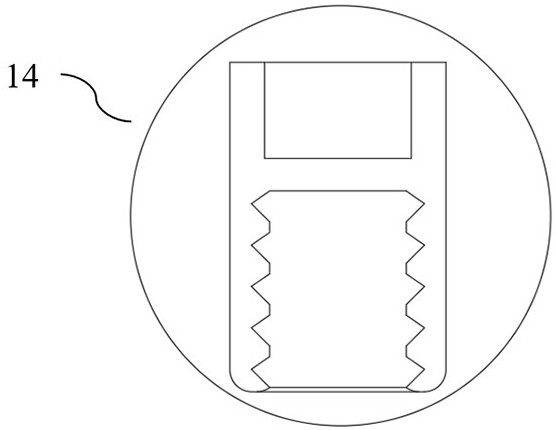
[0095] Specifically, the anchoring part 10 includes a radially shrinkable first support net 11 and a first fixation element 14, the outer peripheral surface of the first support net 11 is provided with several anchor elements 13 for grasping left atrial appendage tissue, and the first fixation element 14 is installed on the end of the first support net 11 close to the connecting part 20, and the first fixing element 14 is detachably connected to the connecting part 20, so that the anchoring part 10 can be separately placed at the left atrial appendage. In a preferred embodiment, as figure 2 As shown, one end of the first fixing element 14 has a cavity structure for fixing the first support net 11 , and the other end has an internal thread structure detachably conne...

Embodiment 2

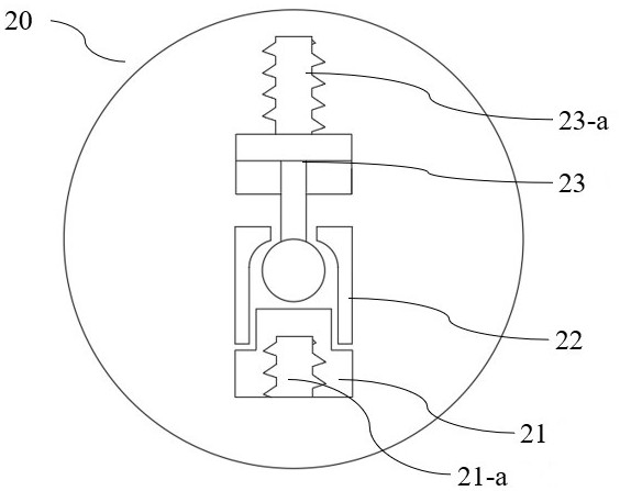
[0112] This embodiment is a left atrial appendage occluder, and the main difference from the first embodiment lies in the specific structure of the connecting part 20, and the same parts will not be repeated here.

[0113] Specifically, as image 3 and Figure 8As shown, the connecting part 20 includes a threaded connector 21 , a hollow limiting element 22 and a clamping element 23 , wherein the hollow limiting element 22 has an open structure at both ends and a spherical cavity inside. One end of the clamping element 23 is rotatably installed inside the spherical cavity to match the spherical cavity, and the other end has an anchor connection structure 23-a. One end of the threaded connector 21 is slidably installed in the hollow limiting element 22 and is located on the same axis, and the other end has a covering portion connecting structure 21-a. It should be noted that the connecting structure 23-a of the anchoring part and the connecting structure 21-a of the covering p...

Embodiment 3

[0122] This embodiment is a left atrial appendage occluder, which is in a parallel relationship with the structural scheme of the connecting part 20 in the second embodiment, and the same parts will not be repeated here.

[0123] Specifically, such as Figure 5 or Figure 21 As shown, the connection part 20 includes a first limiting element 24, a second limiting element 25 and an elastic element 26, wherein the first limiting element 24 and the second limiting element 25 have cavities 27 oppositely arranged, the first The limiting element 24 is installed in the second limiting element 25, and the first limiting element 24 is provided with an inwardly extending first flange 24-a on the side facing the second limiting element 25, and the second limiting element 24 The side of the positioning element 25 facing the first limiting element 24 is provided with a second folded edge 25-a extending outward, and the first folded edge 24-a and the second folded edge 25-a overlap each oth...


PUM

PropertyMeasurementUnit
Lengthaaaaaaaaaa

Abstract

The invention discloses a left auricle occluder and a using method thereof. The left auricle occluder comprises an anchoring part, a connecting part and a covering part which are sequentially connected in the axial direction, the anchoring part comprises a first supporting net capable of contracting in the radial direction and a first fixing element, a plurality of anchoring elements used for grabbing left auricle tissue are arranged on the peripheral surface of the first supporting net, the first fixing element is detachably connected with the connecting part so that the anchoring part can beindependently arranged at the left auricle, the covering part comprises a second supporting net capable of contracting in the radial direction and a second fixing element, the second fixing element is arranged at the end, away from the connecting part, of the second supporting net, and pushing device connecting positions are arranged at the ends, away from the first supporting net, of the first fixing element and the second fixing element respectively. According to the left auricle occluder and the using method thereof, through the specific structures and connection relations of the anchoringpart, the connecting part and the covering part, the purposes that the occluder is flexible to use, and the adaptability of the left auricle occluder to left auricles of various forms is improved areachieved.

Description

technical field [0001] The invention relates to the field of medical instruments, in particular to a left atrial appendage occluder and a method for using the same. Background technique [0002] Percutaneous left atrial appendage occlusion refers to delivering the left atrial appendage occluder to the left atrial appendage of the left atrium of the heart with the help of a slender delivery sheath through percutaneous puncture, that is, using minimally invasive intervention to remove the left atrial appendage. The channel with the left atrium is blocked, so that the blood in the atrium no longer flows into the left atrial appendage, and the thrombus in the left atrial appendage no longer flows into the blood circulation system, thereby achieving the purpose of preventing thromboembolism induced by atrial fibrillation. Since 2001, percutaneous left atrial appendage occlusion has been used in clinical practice. Years of clinical use have shown that percutaneous left atrial appe...

Claims


Application Information

Patent Timeline
IPC IPC(8): A61B17/00
CPCA61B17/0057A61B2017/00606A61B2017/00623A61B17/12122A61B17/12172A61B2017/00477A61B2017/1205A61B2017/00858A61B17/12177A61B2017/00619A61B2017/00853A61B17/12168A61B2017/00592
Inventor 李瑞汤亮赵丹儒闫伟龚善石
Owner 上海介入医疗器械有限公司
Learn More