
Skull drill bit capable of adjusting bone pad thickness

A skull and drill technology, applied in the field of skull drills, can solve the problems of increased operation cost and workload, low safety, and damage to brain tissue

Pending Publication Date: 2020-12-04
CHONGQING XISHAN SCI & TECH
View PDF0 Cites 1 Cited by
  • Summary
  • Abstract
  • Description
  • Claims
  • Application Information

AI Technical Summary

Problems solved by technology

[0003] When the thickness h of the skull 50 is smaller than the spacing S, the inner drill bit has penetrated the skull 50 during drilling, and the outer drill bit has not been in contact with the surface of the skull 50, so that the inner drill bit can continue to feed without support, and damage the brain. organization, less security
That is to say, the distance S between the end face of the inner drill bit and the end face of the outer drill bit of the same type of skull opener is fixed, and it is impossible to safely perform drilling operations on skulls with different thickness d
In this way, for the skulls of different patients, or the skulls 50 of different parts of the same patient, since the thickness d of the skulls 50 is different, it is usually necessary to operate with various types of skull openers, which will increase the operation cost and workload.

Method used


Image

  • Skull drill bit capable of adjusting bone pad thickness
  • Skull drill bit capable of adjusting bone pad thickness
  • Skull drill bit capable of adjusting bone pad thickness

Examples


Embodiment Construction

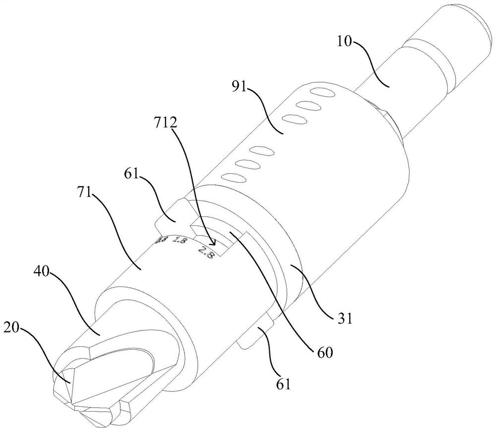
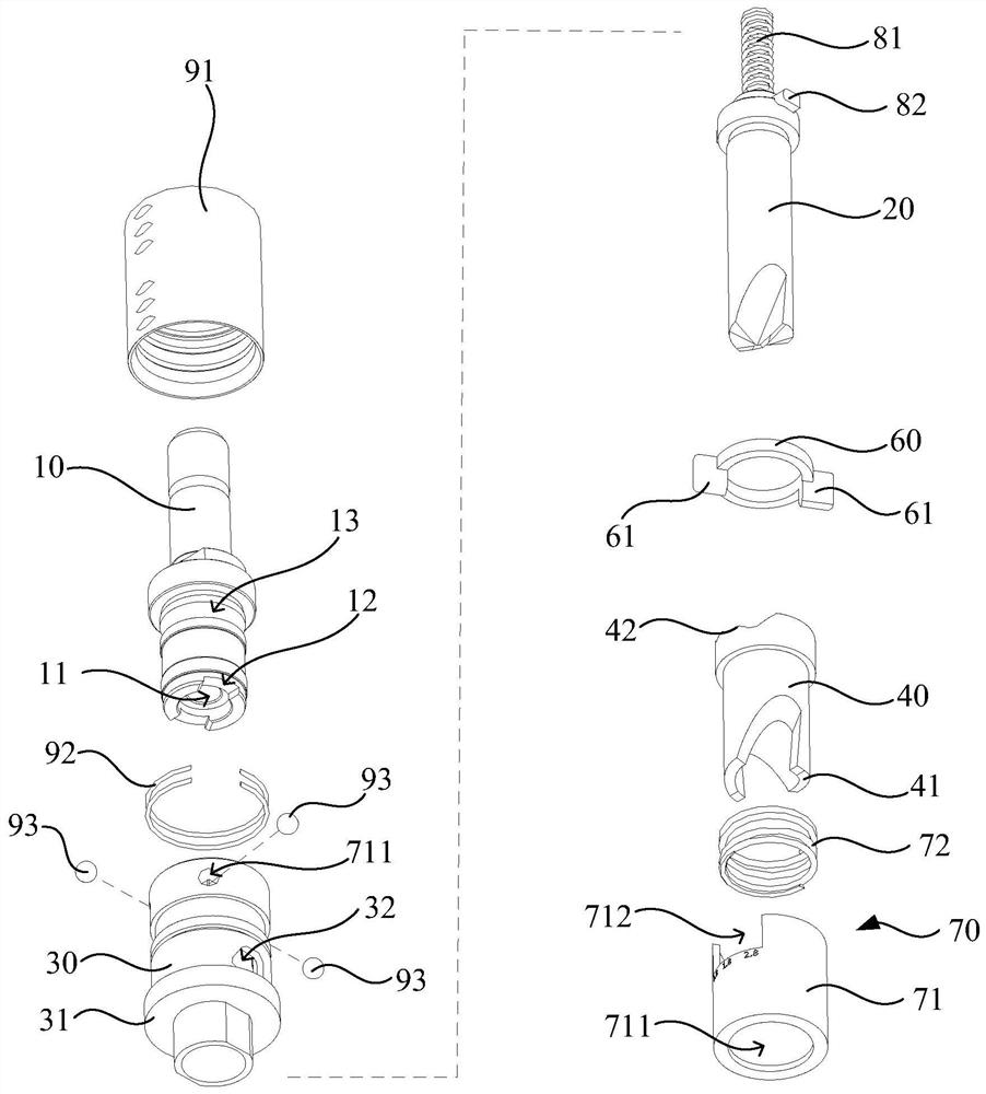
[0038] In order to make the above objects, features and advantages of the present invention more comprehensible, specific implementations of the present invention will be described in detail below in conjunction with the accompanying drawings. In the following description, numerous specific details are set forth in order to provide a thorough understanding of the present invention. However, the present invention can be implemented in many other ways different from those described here, and those skilled in the art can make similar improvements without departing from the connotation of the present invention, so the present invention is not limited by the specific embodiments disclosed below.

[0039] refer to figure 2 and image 3 , figure 2 Schematic diagram showing the structure of a skull drill with adjustable bone pad thickness according to an embodiment of the present invention, image 3 A schematic diagram showing an exploded structure of a skull drill with adjustabl...


PUM


Abstract

The invention relates to a skull drill bit capable of adjusting the bone pad thickness. The skull drill bit capable of adjusting the bone pad thickness comprises a connecting column, an inner drill bit, a transmission sleeve and an outer drill bit, wherein one end of the inner drill bit is in clutch fit with the connecting column, a first drilling surface is arranged at the other end of the innerdrill bit, and the inner drill bit synchronously drives the transmission sleeve to rotate while rotating; the transmission sleeve synchronously drives the outer drill bit to rotate when rotating, anda first through hole is formed in the transmission sleeve; the outer drill bit is provided with a second through hole; the inner drill bit is arranged in the first through hole and the second throughhole; the first drilling surface is located outside the outer drill bit; and the outer drill bit is adjustably arranged on the transmission sleeve in the axial direction of the outer drill bit, and asecond drilling surface is arranged at the end, away from the connecting column, of the outer drill bit. According to the skull drill bit capable of adjusting the bone pad thickness, the position of the outer drill bit can be adjusted according to the thickness d of a bone pad required to be formed by drilling, so that the skull tapper of the same model can adapt to drilling operation of skulls with different thicknesses h and can adapt to drilling operation of skulls of different people or different parts of the skull, the safety performance is guaranteed, and the cost is reduced.

Description

technical field [0001] The invention relates to the technical field of medical instruments, in particular to a skull drill bit with adjustable bone pad thickness. Background technique [0002] Craniotomes are used to drill holes in the skull during neurosurgery. A traditional skull opener includes an inner drill, an outer drill that is sheathed outside the inner drill and rotates synchronously with the inner drill, a connecting column and a motor. The rotating shaft of the motor drives the connecting column to rotate, and the connecting column is clutch-coupled with the inner drill bit. When the inner drill bit drills through the skull, the inner drill bit is separated from the connecting column, so that the inner drill bit and the outer drill bit no longer rotate to drill the skull. like figure 1 As shown, the traditional skull hole opener drills the formed hole on the skull 50 as a stepped hole. After the inner drill bit drills through the skull 50, it is separated from...

Claims


Application Information

Patent Timeline
Patent Type & Authority Applications(China)
IPC IPC(8): A61B17/16
CPCA61B17/1615A61B17/1626A61B17/1695
Inventor 郭毅军杨雨烟
Owner CHONGQING XISHAN SCI & TECH
Learn More