Portable tumour uptake device for oncology department

A portable tumor technology, applied in the medical field, can solve the problems of low surgical precision, tumor clamping, easy to break tumor lesions, etc.

Inactive Publication Date: 2020-12-04
卢乐
View PDF0 Cites 2 Cited by
  • Summary
  • Abstract
  • Description
  • Claims
  • Application Information

AI Technical Summary

Problems solved by technology

[0003] When a surgeon performs an operation on a patient, the tumor is generally extracted with medical tweezers during tumor resection. However, when the tweezers are used to extract the tumor, there are only two stress points on the tumor and the force area is small. If it is too small, the tumor cannot be clamped. If the force is too large, it is easy to crush the tumor, which is very inconvenient, and sometimes even adds some unnecessary difficulties to the operation, because it is easy to destroy the tumor focus with hands or instruments , loses the original shape, which affects the surgeon's judgment of the pathological condition of the lesion from its appearance, and has a certain impact on the further diagnosis of the disease. During the operation, the opening is relatively small, and the tweezers are easy to touch the surrounding tissue and cause damage to the surrounding tissue. , and the process of tumor clipping will lead to tumor rupture. After the rupture, the incomplete tumor will have the risk of implantation and metastasis to other parts. There is no good clamping fixture to stably fix the tumor, which makes it necessary to do fine In the tumor resection operation, the accuracy of the operation is not high, and it takes a long time, so the innovation of the complete tumor removal tool is particularly important

Method used


Image

  • Portable tumour uptake device for oncology department
  • Portable tumour uptake device for oncology department
  • Portable tumour uptake device for oncology department

Examples


Embodiment Construction

[0022] Embodiments of the present invention will be further described in detail below in conjunction with the accompanying drawings.

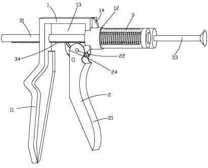
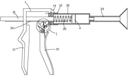
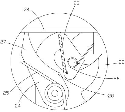
[0023] Figure 1 to Figure 4 It is a structural schematic diagram of the present invention.

[0024] The reference signs are: frame 1, handle 11, fixed head 12, control cavity 13, reinforcing rib 14, operating mechanism 2, pressure handle 21, pivot 22, positioning member 23, driving member 24, torsion spring 25 , reset elastic member 26, push top 27, top angle 28, adsorption mechanism 3, piston rod 31, piston cylinder 32, adsorption head 33, adjusting straight rack 34, spring 35, pressure ring 36, piston assembly 4, front push plate 41. Piston pad 42, rear push plate 43, rear fixed edge 44, front fixed edge 45, installation pipe 46, second fixed convex ring 47.

[0025] Such as Figure 1 to Figure 4 Shown:

[0026] A portable tumor ingester used in oncology, comprising a frame 1, an operating mechanism 2 and an adsorption mechanism 3, the r...


PUM


Abstract

The invention discloses a portable tumour uptake device for the oncology department. The portable tumour uptake device for the oncology department comprises a machine frame, an operating mechanism andan adsorption mechanism; the rear end of the machine frame extends downwards to form a grip; the adsorption mechanism comprises a piston rod, a piston assembly, a piston cylinder and an adsorption head connected to the front end of the piston cylinder; the piston assembly is arranged in the piston cylinder, and can slide along the inner wall of the piston cylinder; the piston rod is connected tothe rear end of the piston assembly; the rear end of the piston cylinder is connected to a fixing head on the machine frame; the rear end of the piston rod penetrates through a through hole in the machine frame, and penetrates out of the rear end of the machine frame; an adjusting straight rack is arranged on the piston rod; the through hole is configured to correspond to the piston rod and the adjusting straight rack in shape so as to prevent the piston rod from rotating, so that the piston rod is guided to move linearly and telescopically; a control cavity communicated with the through holeis formed in the machine frame; the operating mechanism comprises a pressing handle and a pushing and blocking structure; tumour rupture cannot be caused; and it is guaranteed that an operation can becarried out rapidly and effectively.

Description

technical field [0001] The invention relates to the field of medical technology, in particular to a portable tumor uptaker for oncology departments. Background technique [0002] Tumor refers to the new organism formed by the proliferation of local tissue cells under the action of various tumor-causing factors, because this new organism is mostly in the form of space-occupying blocky protrusions, also known as neoplasm. Under the action, a certain cell in the local tissue loses its normal regulation of its growth at the gene level, resulting in abnormal lesions formed by its clonal abnormal proliferation. There are varying degrees of difference. [0003] When a surgeon performs an operation on a patient, the tumor is generally extracted with medical tweezers during tumor resection. However, when the tweezers are used to extract the tumor, there are only two stress points on the tumor and the force area is small. If it is too small, the tumor cannot be clamped. If the force...

Claims


Application Information

Patent Timeline
Patent Type & Authority Applications(China)
IPC IPC(8): A61B90/17
CPCA61B90/17
Inventor 卢乐
Owner 卢乐
Why Eureka
Try Eureka