Blowing device of metal 3D printer

A 3D printer and blower technology, applied in the field of 3D printing, can solve the problems of difficulty in ensuring fluid uniformity and laminar flow, weakening the laminar flow of the protective gas on the surface of the powder bed, and affecting the quality of the molding surface, so as to reduce eddy current and ensure The effect of smooth blending and laminar flow improvement

Pending Publication Date: 2020-12-04
XIAN BRIGHT ADDTIVE TECH CO LTD
View PDF0 Cites 1 Cited by
  • Summary
  • Abstract
  • Description
  • Claims
  • Application Information

AI Technical Summary

Problems solved by technology

This structure will have the following problems: 1) After the gas enters the airflow channel through the air inlet, since there is a baffle with a height h between the air outlet of the airflow channel and the bottom of the housing, the gas will flow into the molding chamber from the air outlet of the airflow channel. homogeneity and swirl (see image 3 ), the generation of eddy current or whether it is strong or not will weaken the laminar flow of the p

Method used


Image

  • Blowing device of metal 3D printer
  • Blowing device of metal 3D printer
  • Blowing device of metal 3D printer

Examples


Example Embodiment

[0028] The blowing device provided by the present invention will be described in detail below with reference to the accompanying drawings and specific embodiments.

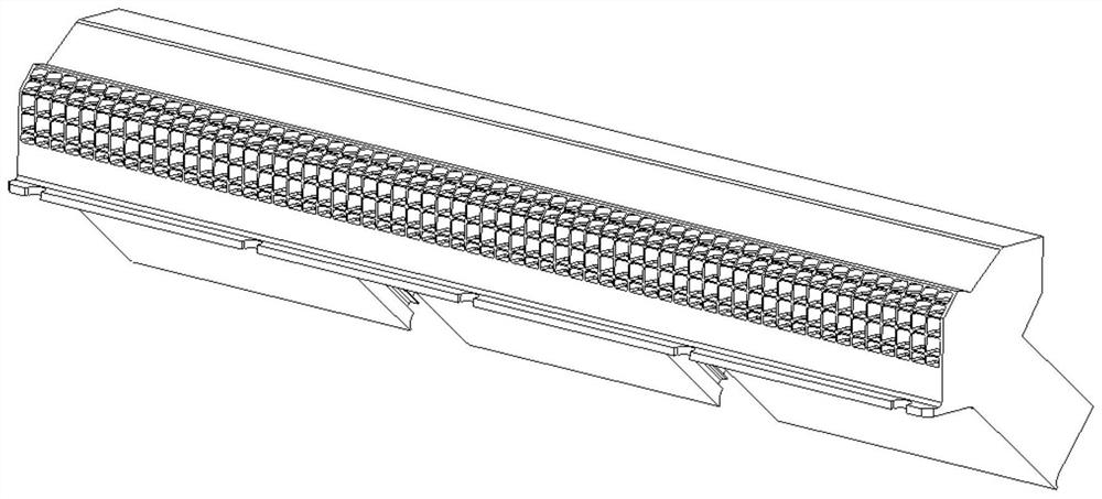
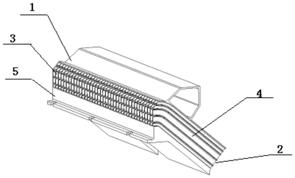
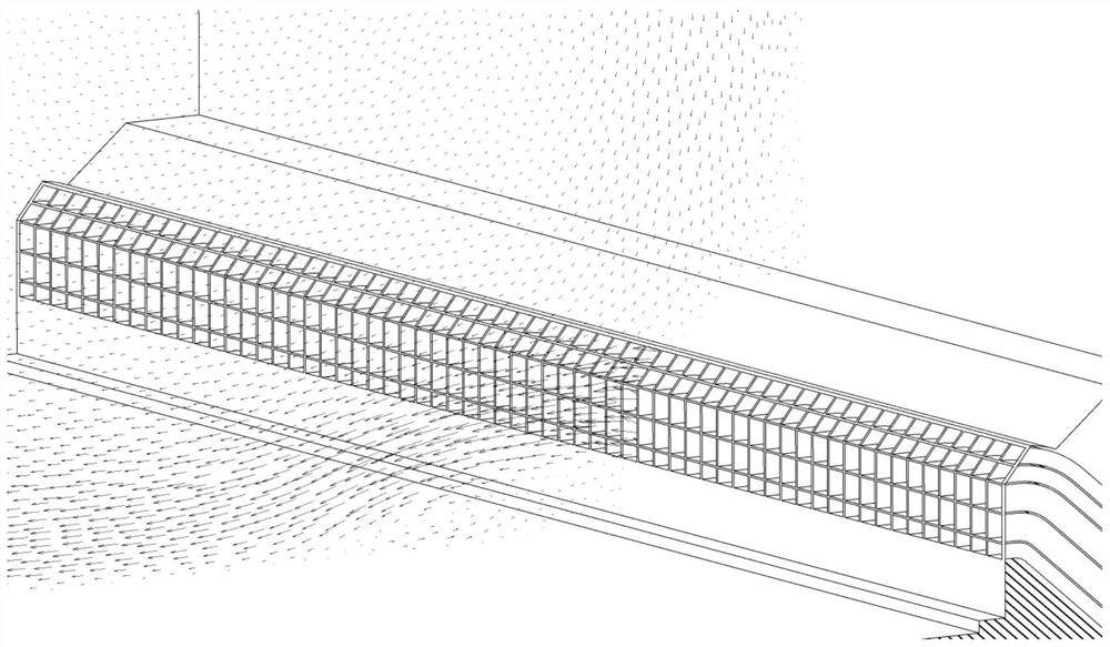
[0029] see Figure 4 , Figure 5 as well as Image 6 , the present invention provides a metal 3D printer blowing device, which is the same as the prior art: the blowing structure includes a casing 1, and the casing 1 is provided with an air inlet 2 and an air outlet 3; Airflow channel 4; Airflow channel 4 includes N layers of flow channels stacked in sequence from top to bottom; N≥2; Air Inlet 2 communicates with Air Outlet 3 through Airflow Channel 4; the lower edge of air outlet 3 and the lower edge of housing 1 There is a baffle 5 with a height of h between them; the difference from the prior art is: the baffle 5 is provided with a bottom flow channel outlet 6, and the bottom flow channel 9 in the airflow channel 4 communicates with the bottom flow channel outlet 6 ; The distance from the lower edge of the b...


PUM


Abstract

The invention belongs to the technical field of 3D printing, and relates to a blowing device of a metal 3D printer. The blowing device comprises a shell, and an air inlet and an air outlet are formedin the shell; an airflow channel is formed in the shell; the airflow channel comprises N layers of flow channels which are sequentially superimposed from top to bottom, wherein N is greater than or equal to two; the air inlet communicates with the air outlet through the airflow channel; a baffle with the height of h is arranged between the lower edge of the air outlet and the lower edge of the shell; a bottom-layer flow channel outlet is formed in the baffle, and the flow channel at the bottommost layer in the airflow channel communicates with the bottom-layer flow channel outlet; the distancebetween the lower edge of the bottom-layer flow channel outlet and the lower edge of the shell is h1, wherein h1 is less than h. According to the blowing device of the metal 3D printer, vortexes at ashielding gas outlet can be effectively reduced, the laminarity of shielding gas on the surface of a powder bed can be obviously improved, and the quality of the forming surface in the printing process is ensured.

Description

technical field [0001] The invention belongs to the technical field of 3D printing, and relates to a blowing device, in particular to a metal 3D printer blowing device. Background technique [0002] Metal 3D printing is a metal rapid prototyping technology. It is a technology that uses powdered metal to construct three-dimensional objects through laser selective sintering. It is a manufacturing method that adds and selectively solidifies metal material powder layer by layer in the molding room. In its molding chamber, there is a shielding gas inlet on one side and a shielding gas outlet on the other. Oxidation of the surface is avoided by the applied shielding gas forming a laminar shielding gas flow above the forming area. [0003] see figure 1 as well as figure 2 , is a structural schematic diagram of a blowing device used in a 3D printer in the prior art and a schematic cross-sectional flow channel diagram of the blowing device. The blowing device includes a housing,...

Claims


Application Information

Patent Timeline
IPC IPC(8): B22F3/105B33Y30/00B33Y40/00
CPCB22F3/003B33Y30/00B33Y40/00
Inventor 赵彦辰
Owner XIAN BRIGHT ADDTIVE TECH CO LTD
Why Eureka
Try Eureka