Eureka AIR delivers breakthrough ideas for toughest innovation challenges, trusted by R&D personnel around the world.

Vertical lathe special for machining large-diameter shield body

A technology with large diameter and shield body, which is applied in the direction of metal processing equipment, metal processing machinery parts, turning equipment, etc. It can solve the problems of affecting processing accuracy, increased workload, and deformation of shield body, so as to improve processing accuracy and avoid potential safety hazards , The effect of shortening the processing period

Pending Publication Date: 2020-12-04
CHINA RAILWAY SCI & IND GRP RAIL TRANSPORTATION EQUIP LIMITED
View PDF0 Cites 3 Cited by
  • Summary
  • Abstract
  • Description
  • Claims
  • Application Information

AI Technical Summary

Problems solved by technology

[0002] With the continuous development of underground space construction and the increasing demand for underground space, the demand for the diameter of the shield machine is also increasing. The ten-meter vertical lathe is used to process the conventional shield body. Theoretically, the ten-meter large-diameter shield body is The processing limit of the 10-meter vertical lathe, but the weight of the front middle shield of the shield body with a diameter of 8600mm is 160 tons in actual conditions, which is already the load limit of the ten-meter vertical lathe. When the ten-meter vertical lathe is processing the front middle shield of the 8600mm shield body, Turning over twice and assembling three times not only caused the deformation of the shield body to affect the machining accuracy, but also slowed down the cutting speed, which led to an increase in workload and could not meet the needs of shield machine processing

Method used


Image

  • Vertical lathe special for machining large-diameter shield body
  • Vertical lathe special for machining large-diameter shield body
  • Vertical lathe special for machining large-diameter shield body

Examples


Embodiment Construction

[0018] In order to make the purposes, technical solutions and advantages of the embodiments of the present application clearer, the technical solutions in the embodiments of the present application will be clearly and completely described below in conjunction with the drawings in the embodiments of the present application. Obviously, the described embodiments It is a part of the embodiments of this application, not all of them. The components of the embodiments of the application generally described and illustrated in the figures herein may be arranged and designed in a variety of different configurations.

[0019] Accordingly, the following detailed description of the embodiments of the application provided in the accompanying drawings is not intended to limit the scope of the claimed application, but merely represents selected embodiments of the application. Based on the embodiments in this application, all other embodiments obtained by persons of ordinary skill in the art w...


PUM


Abstract

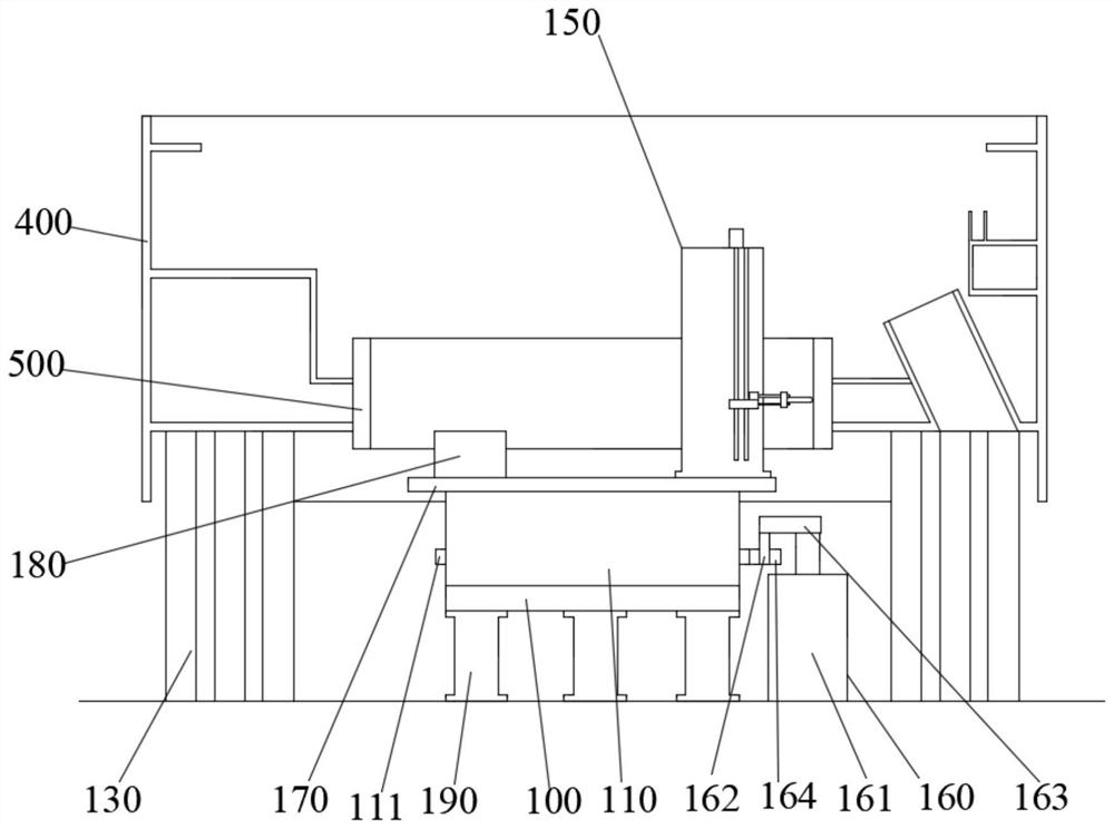
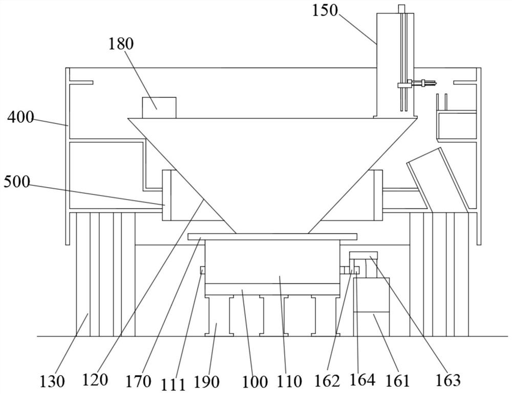
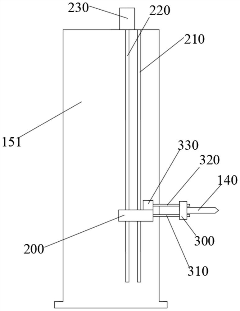
The invention provides a vertical lathe special for machining a large-diameter shield body and relates to the field of shield machine devices. The vertical lathe special for machining the large-diameter shield body comprises a working table supporting plate, a working table installed on the working table supporting plate in a rotating manner, a supporting base in an inverted circular truncated cone shape, multiple shield body supporting stand columns arranged at intervals in the peripheral direction of the working table, a machining tool, and a feeding assembly used for driving the machining tool to be lifted and moving in the horizontal straight line, wherein the supporting base is detachably connected to the working table. The feeding assembly is arranged to be detachably connected to the top edge of the working table or the top edge of the supporting base. A revolution assembly used for driving the working table to rotate is further connected to the working table. According to the vertical lathe special for machining the large-diameter shield body, all the shield body is machined in place through one-time clamping, potential safety hazards caused to the large-diameter shield body due to multiple times of clamping are avoided, machining precision can be improved, and the earlier and middle shield machining period of the large-diameter shield body is shortened.

Description

technical field [0001] The present application relates to the field of shield machine devices, in particular to a special vertical lathe for processing large-diameter shield bodies. Background technique [0002] With the continuous development of underground space construction and the increasing demand for underground space, the demand for the diameter of the shield machine is also increasing. The ten-meter vertical lathe is used to process the conventional shield body. Theoretically, the ten-meter large-diameter shield body is The processing limit of the 10-meter vertical lathe, but the weight of the front middle shield of the shield body with a diameter of 8600mm is 160 tons in actual conditions, which is already the load limit of the ten-meter vertical lathe. When the ten-meter vertical lathe is processing the front middle shield of the 8600mm shield body, Turning over twice and assembling three times not only caused the deformation of the shield body to affect the machin...

Claims


Application Information

Patent Timeline
Patent Type & Authority Applications(China)
IPC IPC(8): B23B5/00B23B21/00B23Q1/25
CPCB23B5/00B23Q1/25
Inventor 王承海汪涛杨凡程俊秦培兵陈汉龙于华森刘成伟韩玉夏威万骁黄俊文
Owner CHINA RAILWAY SCI & IND GRP RAIL TRANSPORTATION EQUIP LIMITED
Why Eureka
Eureka Blog
Learn More