Auxiliary tool supporting device for welding of low-temperature container

A technology for auxiliary tooling and cryogenic containers, which is applied in auxiliary devices, welding/cutting auxiliary equipment, welding equipment, etc., can solve the problems of low welding efficiency, damage to the inner wall force of the cylinder, time-consuming and laborious disassembly, etc., and achieves simple structure and convenient operation. , the effect of preventing deformation

Inactive Publication Date: 2020-12-04
JIUJIANG HAITIAN EQUIP MFG CO LTD
View PDF5 Cites 4 Cited by
  • Summary
  • Abstract
  • Description
  • Claims
  • Application Information

AI Technical Summary

Problems solved by technology

With this kind of fixed support frame, when the size of the cylinder parts changes, it is necessary to equip a fixed support frame with many specifications to meet the production requirements, and after the fixed support frame is used many times, the end of the fixed support frame is repeatedly Welding and cutting, its size becomes shorter and it needs to repair a section of steel plate before it can be used. Its versatility is poor. It takes a long time to install and adjust and position the fixed support frame during welding, which affects the welding efficiency. At the same time, the welding efficiency is low and increases The labor intensity of the workers, especially the time-consuming and labor-intensive disassembly, can easily damage the inner wall of the cylinder; and it cannot be adjusted according to the actual length and height of the cylinder

Method used


Image

  • Auxiliary tool supporting device for welding of low-temperature container
  • Auxiliary tool supporting device for welding of low-temperature container
  • Auxiliary tool supporting device for welding of low-temperature container

Examples


Embodiment Construction

[0028] The following will clearly and completely describe the technical solutions in the embodiments of the present invention with reference to the accompanying drawings in the embodiments of the present invention. Obviously, the described embodiments are only some, not all, embodiments of the present invention. Based on the embodiments of the present invention, all other embodiments obtained by persons of ordinary skill in the art without creative efforts fall within the protection scope of the present invention.

[0029] In the description of the present invention, it should be understood that the terms "opening", "upper", "lower", "bottom", "top", "side", "inner wall", "circumferential side", "surrounding" Indicating orientations or positional relationships, etc., are only for the convenience of describing the present invention and simplifying the description, but do not indicate or imply that the components or elements referred to must have a specific orientation, be constr...


PUM


Abstract

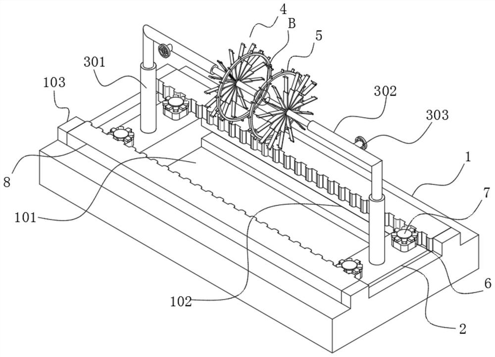
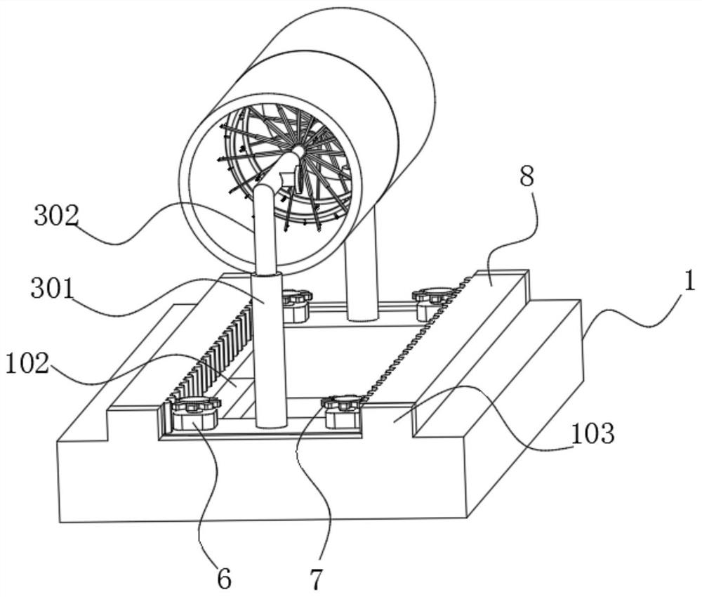
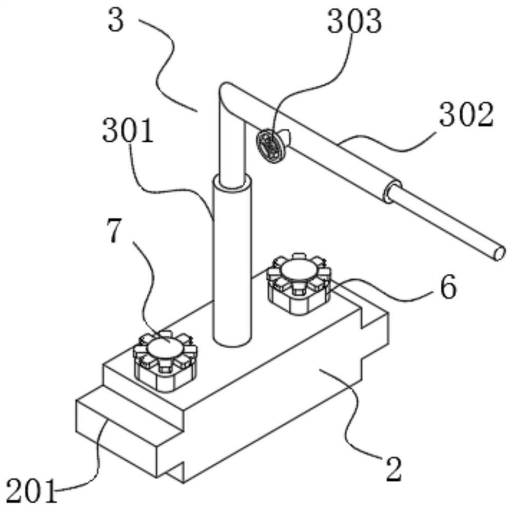
The invention discloses an auxiliary tool supporting device for low-temperature container welding, and relates to the technical field of low-temperature container welding auxiliary tools. The auxiliary tool supporting device comprises a supporting platform, sliding blocks, adjusting rod assemblies, supporting adjusting frames and lug-ring-shaped rails; the sliding blocks are in sliding fit with the supporting platform; the adjusting rod assemblies are fixedly installed on the peripheral side faces of the adjusting rod assemblies; the supporting adjusting frames are in meshing transmission fitwith the lug-ring-shaped rails; the sliding rails are in sliding fit with sliding groove channels; rotating motors are symmetrically and fixedly mounted at the tops of the sliding blocks; the output end of each rotating motor is fixedly connected with a rotating gear; and the adjusting rod assembly comprises hydraulic cylinders. According to the auxiliary tool supporting device, by sliding of thetwo sliding blocks and adjustment between the adjusting rod assemblies, cylinders of different lengths and sizes can be welded at different heights; and seamless cutting-fit sleeves abut against the inner walls of the cylinders through the supporting adjusting frames and are fixed through annular lug chains, so that the situation that the cylinders are heated or deformed due to external force in the welding process is prevented.

Description

technical field [0001] The invention belongs to the technical field of low-temperature container welding auxiliary tooling technology, and in particular relates to an auxiliary tooling support device for low-temperature container welding. Background technique [0002] Large-scale cryogenic liquid storage tanks are rolled and welded by steel plates. In order to prevent the deformation of the cylinder joints during the butt welding of the cylinder joints, it is necessary to set up auxiliary supporting tools in the cylinder joints. The existing auxiliary support tooling generally adopts a "meter"-shaped fixed support frame welded by steel plates or steel pipes. The end of the fixed support frame is welded on the inner wall of the cylinder part. Usually, a cylinder section requires Two or three fixed support frames can prevent the deformation of the cylinder section when the cylinder is welded, and the fixed support frames can be removed after the cylinder is welded. With this ...

Claims


Application Information

Patent Timeline
Patent Type & Authority Applications(China)
IPC IPC(8): B23K37/047
CPCB23K37/047
Inventor 孙俊峰于会敏胡敏胥陈瑞芬
Owner JIUJIANG HAITIAN EQUIP MFG CO LTD
Why Eureka
Try Eureka