Stool coloring device for furniture processing
A bench and furniture technology, applied in the field of bench coloring devices for furniture processing, can solve the problems of troublesome cleaning, manpower consumption, cumbersome operation process, etc., and achieve the effects of avoiding contact, saving manpower, and simple operation
- Summary
- Abstract
- Description
- Claims
- Application Information
AI Technical Summary
Problems solved by technology
Method used
Image
Examples
Embodiment 1
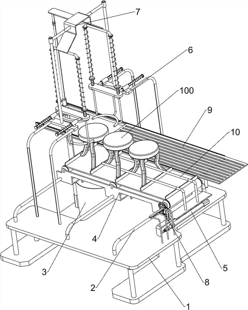
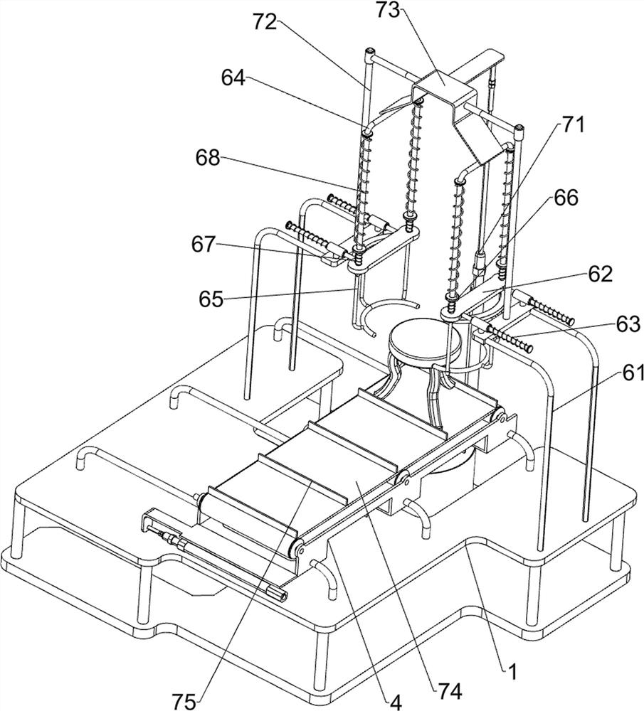
[0025] A bench coloring device for furniture processing, such as Figure 1-2 As shown, it includes a support base 1, a first guide rail 2, a liquid storage tank 3, a sliding frame 4, and a first cylinder 5. The top of the support base 1 is connected with a plurality of first guide rails 2 at even intervals, and the top left side of the support base 1 is connected to There is a liquid storage barrel 3, a sliding frame 4 is slidably connected between multiple first guide rails 2, a first cylinder 5 is installed on the right side of the top of the support seat 1, and the telescopic rod of the first cylinder 5 is connected with the sliding frame 4, and also includes There are a sliding assembly 6 and a pushing assembly 7, the supporting base 1 is provided with a sliding assembly 6, between the supporting base 1 and the sliding frame 4 is provided a pushing assembly 7, and the pushing assembly 7 is connected to the sliding assembly 6 through transmission.
[0026] The sliding assem...
Embodiment 2
[0030] On the basis of Example 1, such as Figure 4 As shown, a rotating assembly 8 is also included. The rotating assembly 8 includes a connecting frame 81, a drive rack 82, a rotating shaft 83, a one-way gear 84 and a bevel gear 85. The right side of the top of the support base 1 is connected with a connecting frame 81. The connecting frame 81 is connected with driving rack 82, and the right side of sliding frame 4 is connected with rotating shaft 83 in a rotating manner, and is connected with one-way gear 84 on rotating shaft 83, and one-way gear 84 can mesh with driving rack 82, and rotating shaft 83 and conveyor belt 74 All bevel gears 85 are connected on the power transmission shafts, and the two bevel gears 85 mesh with each other.
[0031]The sliding frame 4 drives the rotating shaft 83 to move back and forth when reciprocating back and forth, and the reciprocating movement of the rotating shaft 83 drives all the devices on it to reciprocate back and forth together. Wh...
Embodiment 3
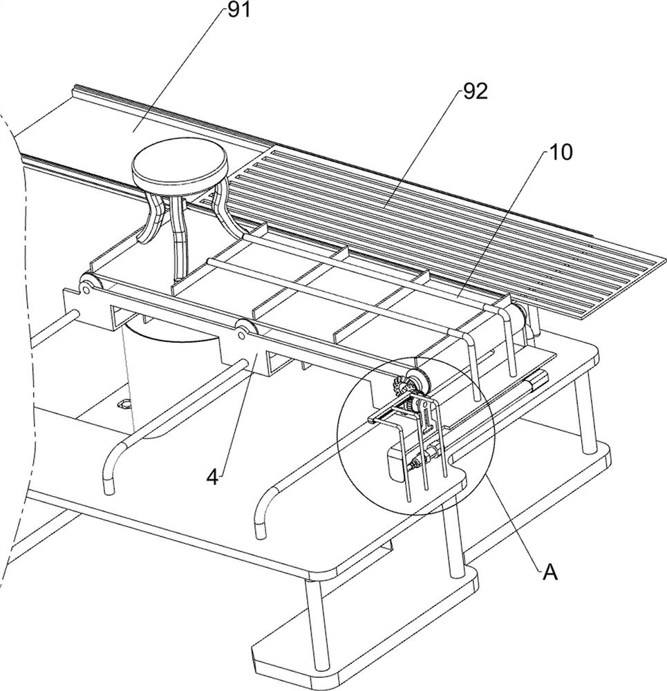
[0033] On the basis of Example 2, such as image 3 As shown, it also includes a placement assembly 9, the placement assembly 9 includes a fixing plate 91 and a placement plate 92, the top rear side of the support base 1 is connected with the fixing plate 91, and the fixing plate 91 is slidably connected with the placement plate 92.
[0034] When the curved clamping rod 65 loosens the painted bench 100, the loosened bench 100 can be manually placed on the placement board 92, thereby making it easier for the manpower to place the bench 100.
[0035] Such as image 3 As shown, a limit rod 10 is also included, and the front and rear sides of the top of the sliding frame 4 are connected with limit rods 10 .
[0036] When the bench 92 is placed, it can be limited by the limit rod 10 .
PUM
 Abstract
Description
Claims
Application Information
 - R&D
- Intellectual Property
- Life Sciences
- Materials
- Tech Scout
- Unparalleled Data Quality
- Higher Quality Content
- 60% Fewer Hallucinations
Browse by: Latest US Patents, China's latest patents, Technical Efficacy Thesaurus, Application Domain, Technology Topic, Popular Technical Reports.
© 2025 PatSnap. All rights reserved.Legal|Privacy policy|Modern Slavery Act Transparency Statement|Sitemap|About US| Contact US: help@patsnap.com


