Air suction device of plastic vacuum forming machine

A technology of suction device and blister machine, which is applied in the field of mechanical equipment, can solve problems such as poor stability, achieve the effect of reducing the requirement of matching accuracy, reducing costs, and avoiding the restriction of gas flow

Pending Publication Date: 2020-12-04
温岭市新河食品机械厂
View PDF1 Cites 0 Cited by
  • Summary
  • Abstract
  • Description
  • Claims
  • Application Information

AI Technical Summary

Problems solved by technology

[0005] The purpose of the present invention is to solve the above-mentioned problems in the existing technology, and propose a suction device of a plastic suction machine to solve the problem that the suction device of the existing plastic suction machine is stable in order to realize the movement of the suction pipe in two directions. sex problem

Method used


Image

  • Air suction device of plastic vacuum forming machine
  • Air suction device of plastic vacuum forming machine
  • Air suction device of plastic vacuum forming machine

Examples


Embodiment 1

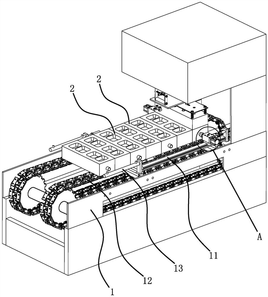
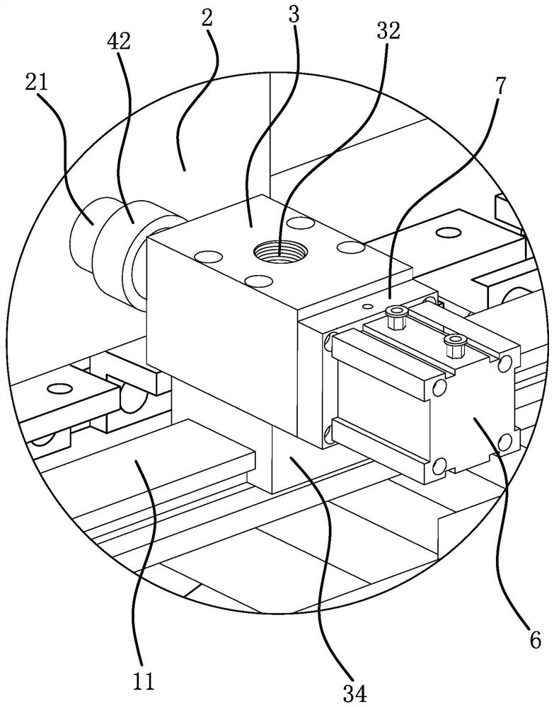
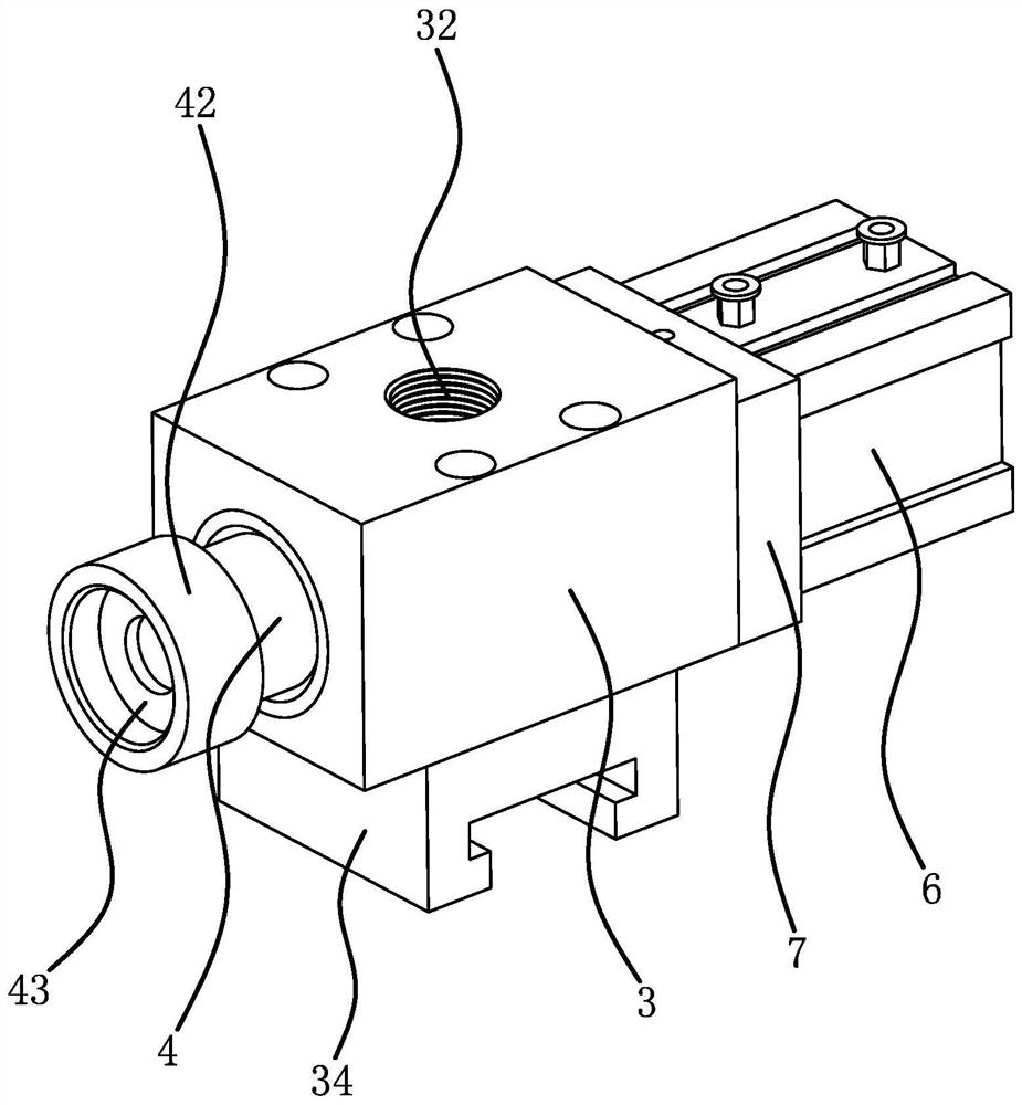
[0036] Such as figure 1 As shown, a suction device of a blister machine, the blister machine includes a frame 1, a conveyor chain 12 is provided on the frame 1, and a plurality of molds 2 are connected to the conveyor chain 12, and the multiple molds 2 are arranged in sequence And move circularly with the conveying chain 12, when the mold 2 moves to the top, the opening of the mold 2 faces upwards, and there is a connecting pipe 21 on the side of the mold 2, which is used to connect the suction device, and the suction device can suck the inner cavity of the mold 2. Gas to achieve blister. combine figure 2 , image 3 As shown, a guide rail 11 is also fixed on the frame 1. The guide rail 11 is arranged along the moving direction of the mold 2. The air suction device includes a slide seat 3, an air suction pipe 4 and a drive cylinder 6. The slide seat 3 is in the shape of a rectangular block. A slider 34 is fixed on the bottom surface of the slider 3, and the slider 34 is sli...

Embodiment 2

[0040] The suction device of this blister machine is basically the same as that of Embodiment 1, the differences are as Figure 6 , Figure 7 As shown, the two sliding sleeves 5 are fixed with the suction pipe 4, and the two sliding sleeves 5 are slidably connected in the guide hole 31, and the outer peripheral walls of the two sliding sleeves 5 form a sliding guide fit with the guide hole 31 wall. , the air hole 41 is opened on the side wall of the suction pipe 4 and communicates with the suction chamber 33 all the time. When the driving cylinder 6 drives the suction pipe 4 to stretch out, the suction chamber 33 communicates with the suction hole 32. When the driving cylinder 6 drives the suction pipe 4 to retract inwardly, the outer peripheral wall of the sliding sleeve 5 blocks the suction hole 32 .

Embodiment 3

[0042] The suction device of this blister machine is basically the same as that of Embodiment 1, the differences are as Figure 8 , Figure 9 As shown, the air suction device does not include the sliding sleeve 5, but the air suction pipe 4 is directly matched with the guide hole 31, that is, the outer peripheral wall of the air suction pipe 4 is slidingly and guidedly matched with the wall of the guide hole 31, and the outer wall of the air suction pipe 4 Grooves are opened in the upper direction to form the suction cavity 33, and the air passage 41 is directly connected to the suction cavity 33. When the driving cylinder 6 drives the suction pipe 4 to extend outward, the suction cavity 33 communicates with the suction hole 32. When the driving cylinder 6 drives the suction pipe 4 to retract inwardly, the peripheral wall of the suction pipe 4 blocks the suction hole 32 .


PUM


Abstract

The invention provides an air suction device of a plastic vacuum forming machine, and belongs to the technical field of mechanical equipment. The problem that an air suction device of an existing plastic vacuum forming machine is poor in stability due to the fact that an air suction pipe moves in two directions is solved. According to the air suction device of the plastic vacuum forming machine, the plastic vacuum forming machine comprises a machine frame and a guide rail arranged on the machine frame; the air suction device comprises an air suction pipe and a driving piece; the air suction device further comprises a sliding base arranged on the guide rail in a sliding mode; a guide hole and an air suction hole communicating with the guide hole are formed in the sliding base; the air suction pipe is arranged in the guide hole in a sliding and penetrating mode; the driving piece is arranged on the sliding seat and can drive the air suction pipe to stretch out and draw back; an air passing hole is formed in the air suction pipe; and the air passing hole can communicate with the air suction hole when the air suction pipe stretches out, and the air passing hole and / or the air suction hole can be blocked when the air suction pipe retracts inwards. The air suction device of the plastic vacuum forming machine is good in stability.

Description

technical field [0001] The invention belongs to the technical field of mechanical equipment and relates to an air suction device of a plastic suction machine. Background technique [0002] Blister molding machine, also called thermoplastic molding machine, is a machine that absorbs heated and plasticized thermoplastic coils such as PVC, PE, PP, PET, HIPS, etc. into various shapes of packaging and decoration boxes, frames and other products. The vacuum suction generated by the vacuum pump can absorb the heated and softened thermoplastic sheet into various shapes of vacuum covers, blister trays, blisters, etc. gas getter. [0003] As disclosed in the patent document (application number: 201811145094.6), the circulating plastic suction mechanism includes a conveying plastic suction workbench and a sliding vacuum suction device. A plurality of circulation plates are laid on the conveying chain of the conveyance plastic suction workbench, and the circulation plate It includes a...

Claims


Application Information

Patent Timeline
IPC IPC(8): B29C51/10B29C51/40
CPCB29C51/10B29C51/40
Inventor 沈正昌
Owner 温岭市新河食品机械厂
Why Eureka
Try Eureka