A 3D printing nozzle for printing clothing

A 3D printing and nozzle technology, applied in the field of 3D printing nozzles, can solve the problems of slow wire melting, nozzle blockage, low work efficiency, etc.

Active Publication Date: 2022-03-22
东北师范大学人文学院
View PDF9 Cites 0 Cited by
  • Summary
  • Abstract
  • Description
  • Claims
  • Application Information

AI Technical Summary

Problems solved by technology

[0002] With the increasing progress of 3D printing technology, 3D printing technology has gradually entered the clothing market. The 3D printing of clothing includes the overall printing of finished clothing, printing of clothing components, printing of accessories on clothing, etc., due to the principle of additive manufacturing of 3D printing Compared with today's subtractive manufacturing of clothing, it will not cause waste of raw materials, so it has a good application prospect. The materials for 3D printing are roughly divided into solid and liquid. Medium-extrusion is used for stacking, and liquid materials are formed by ultraviolet light solidification. The existing solid wires are generally pushed into the high-temperature cavity by rollers, and after melting a section, the subsequent wires continue to be pushed forward. The slow speed makes the work efficiency low, and it will cause the following wire to soften in advance and it is difficult to push the material in the molten state, and the partially melted and partially solid wire is likely to cause nozzle blockage. A 3D printing nozzle is designed to solve the above problems.

Method used


Image

  • A 3D printing nozzle for printing clothing
  • A 3D printing nozzle for printing clothing
  • A 3D printing nozzle for printing clothing

Examples


Embodiment Construction

[0015] In order to make the purpose, technical solutions and advantages of the embodiments of the present invention clearer, the technical solutions in the embodiments of the present invention will be clearly and completely described below in conjunction with the drawings in the embodiments of the present invention. Obviously, the described embodiments It is a part of embodiments of the present invention, but not all embodiments. Based on the embodiments of the present invention, all other embodiments obtained by persons of ordinary skill in the art without creative efforts fall within the protection scope of the present invention.

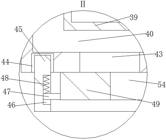
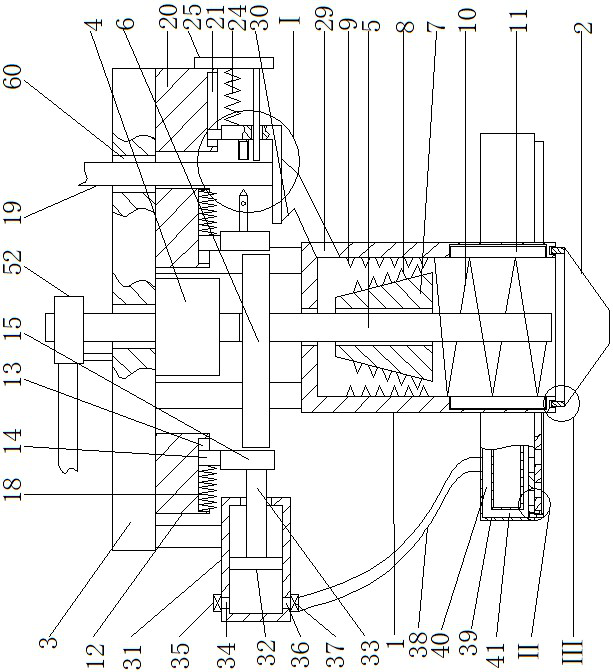
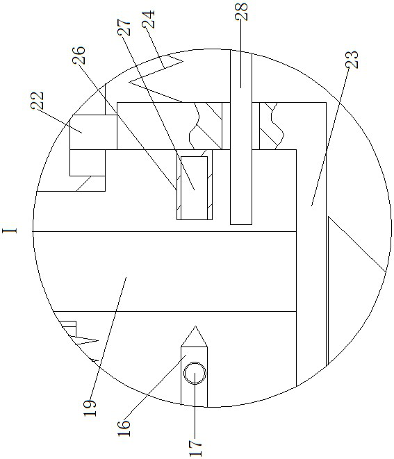
[0016]A 3D printing nozzle for printing clothing, as shown in the figure, includes a nozzle body, the nozzle body includes a nozzle 1 with an open lower end and a nozzle 2 connected to the lower end of the nozzle 1, and the top of the nozzle 1 is fixedly connected with a bracket. Horizontal plate 3, the bottom center of horizontal plate 3 is fixed...


PUM


Abstract

A 3D printing nozzle for printing clothing, including a nozzle body, the nozzle body includes a nozzle with an open lower end and a nozzle connected to the lower end of the nozzle, the top of the nozzle is fixedly connected to a horizontal plate through a bracket, and the center of the bottom of the horizontal plate A motor with the output shaft facing down is fixedly installed, the lower end of the output shaft of the motor is fixedly connected with a rotating shaft, a through hole is opened at the center of the top of the nozzle, the upper outer side of the rotating shaft is fixed with a cam, and the outer wall of the frustum-shaped cylinder is vertically and uniformly fixed and installed There are several first cutting blades. The invention realizes the automatic cutting of solid wire rods through the L-shaped plate, and the rotation of the first cutting blade is driven by the rotating shaft to cooperate with the second cutting blade to gradually chop the cut solid wire rods so that they can be cut quickly when passing through the heating device. For melting, the rotating shaft drives the blades of the auger to rotate so that it can extrude the melted wire outward. The invention improves the melting speed and solidification speed of the solid wire, thereby improving work efficiency.

Description

technical field [0001] The invention belongs to the field of 3D printing nozzles, in particular to a 3D printing nozzle for printing clothing. Background technique [0002] With the increasing progress of 3D printing technology, 3D printing technology has gradually entered the clothing market. The 3D printing of clothing includes the overall printing of finished clothing, printing of clothing components, printing of accessories on clothing, etc., due to the principle of additive manufacturing of 3D printing Compared with today's subtractive manufacturing of clothing, it will not cause waste of raw materials, so it has a good application prospect. The materials for 3D printing are roughly divided into solid and liquid. Medium-extrusion is used for stacking, and liquid materials are formed by ultraviolet light solidification. The existing solid wires are generally pushed into the high-temperature cavity by rollers, and after melting a section, the subsequent wires continue to ...

Claims


Application Information

Patent Timeline
Patent Type & Authority Patents(China)
IPC IPC(8): B29C64/118B29C64/209B29C64/295B29C64/314B33Y30/00B33Y40/10
CPCB29C64/118B29C64/209B29C64/295B29C64/314B33Y30/00B33Y40/10
Inventor 杨雪松张秀芳方毅殷冰瑶李白
Owner 东北师范大学人文学院
Why Eureka
Try Eureka