Convenient-to-use textile embroidery machine for textile processing
An embroidery machine, a convenient technology, applied in the textile field, can solve the problems affecting the moving distance of the needle, affecting the accuracy of the needle, and pattern defects, etc., to achieve the effect of unaffected moving distance, enhanced friction, and preventing accuracy
- Summary
- Abstract
- Description
- Claims
- Application Information
AI Technical Summary
Problems solved by technology
Method used
Image

Examples
Embodiment 1
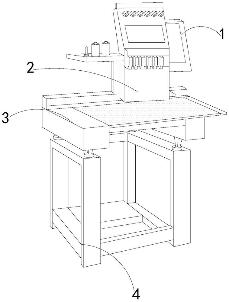
[0023] Such as Figure 1-Figure 5 Shown:
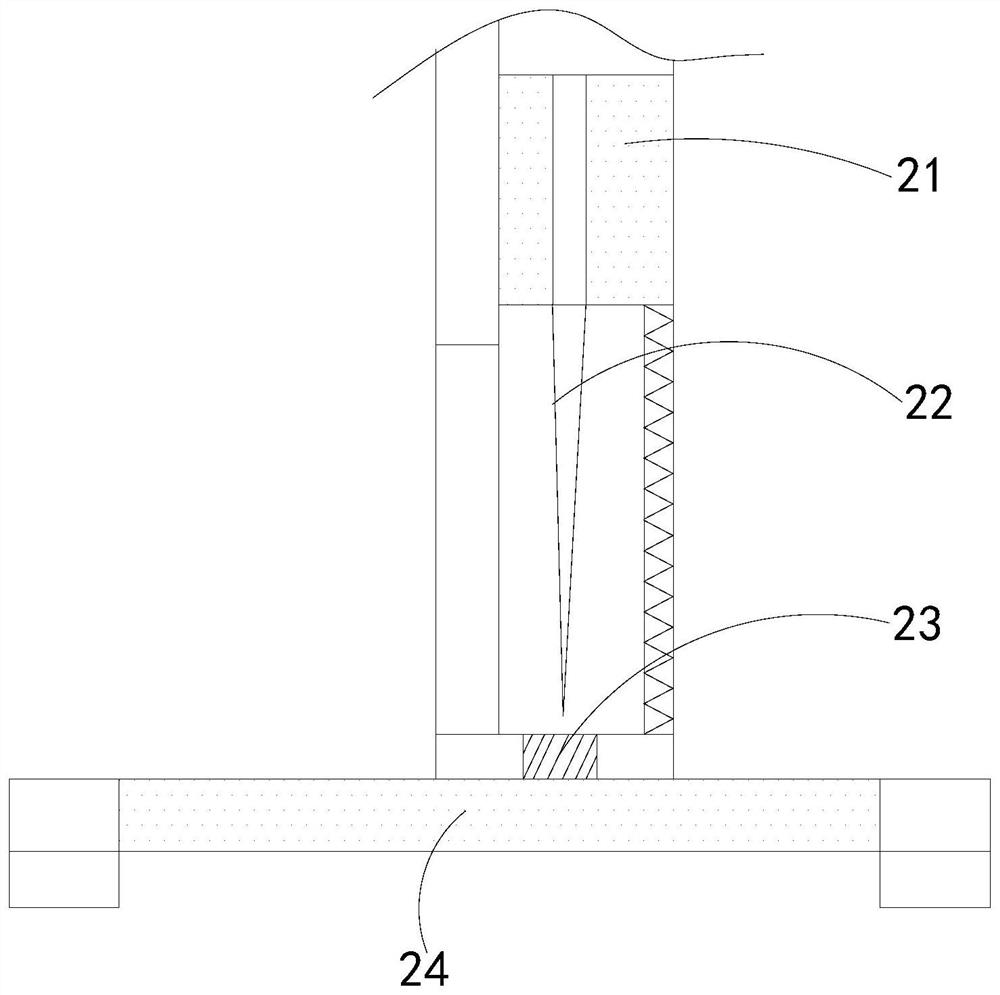
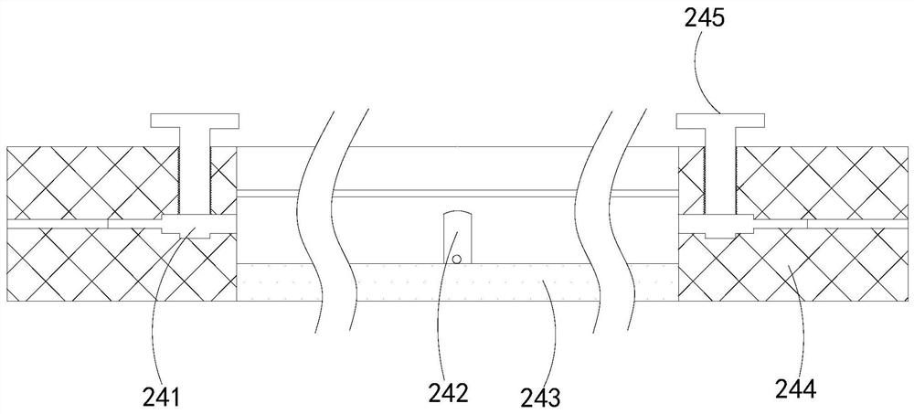
[0024] The present invention is an easy-to-use textile embroidery machine for textile processing. Its structure includes a control panel 1, an embroidery mechanism 2, a fixing frame 3, and a support frame 4. The control panel 1 is embedded and fixed at the front end of the embroidery mechanism 2, and the fixing frame 3 is installed on the upper end of the support frame 4, the embroidery mechanism 2 is located above the fixed frame 3, the embroidery mechanism 2 is provided with a lifter 21, embroidery needles 22, embroidery frames 23, and a fixing mechanism 24, and the embroidery needles 22 are installed on the lifting Inside the device 21, the embroidery frame 23 is attached to the surface of the fixing mechanism 24, the upper left end of the embroidery frame 23 is connected to the lower end of the lifter 21, the fixing mechanism 24 is installed inside the fixing frame 3, and the embroidery frame 23 The upper end of the right side is...
Embodiment 2
[0031] Such as Figure 6-Figure 7 Shown:
[0032]Wherein, the embroidery frame 23 is provided with a shrinkage rod w1, a blocking mechanism w2, a force-bearing hole w3, a force-receiving block w4, a limit rod w5, and a welding plate w6, and the shrinkage rod w1 is attached to the lower end of the welding plate w6. The preventing mechanism w2 is embedded on the outside of the limit rod w5, the limit rod w5 is installed on the outside of the force receiving block w4, the force receiving hole w3 is located inside the force receiving block w4, and the force receiving hole w3 and the fixing mechanism 24 Located on the same central axis, the preventing mechanism w2 rings around the outside of the force-bearing block w4, and a limit spring with the same elastic potential energy is provided inside the end point of the limit rod w5 connected to the force-bearing block w4, so that the preventing mechanism w2 is in the The same horizontal plane enhances the synchronization effect when i...
PUM
 Abstract
Description
Claims
Application Information
 - R&D Engineer
- R&D Manager
- IP Professional
- Industry Leading Data Capabilities
- Powerful AI technology
- Patent DNA Extraction
Browse by: Latest US Patents, China's latest patents, Technical Efficacy Thesaurus, Application Domain, Technology Topic.
© 2024 PatSnap. All rights reserved.Legal|Privacy policy|Modern Slavery Act Transparency Statement|Sitemap