
Bridge head highway subgrade structure
A subgrade and highway technology, applied in roads, roads, buildings, etc., can solve the problems of subgrade fission, poor functionality, lack of bearing stability, etc. Effect
- Summary
- Abstract
- Description
- Claims
- Application Information
AI Technical Summary
Problems solved by technology
Method used
Image

Examples
Embodiment Construction
[0030] The present invention will be described in detail below in conjunction with the accompanying drawings, so that those of ordinary skill in the art can implement it after referring to this specification.
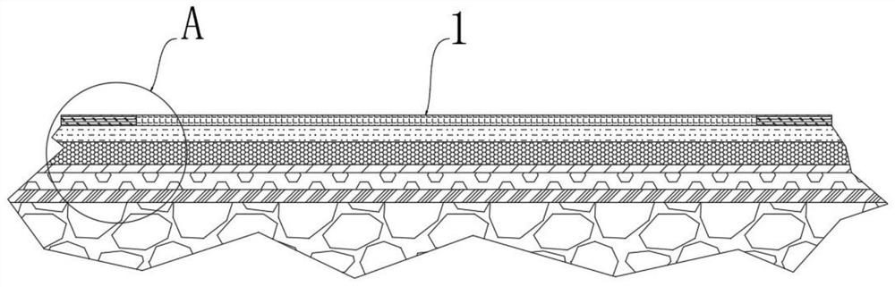
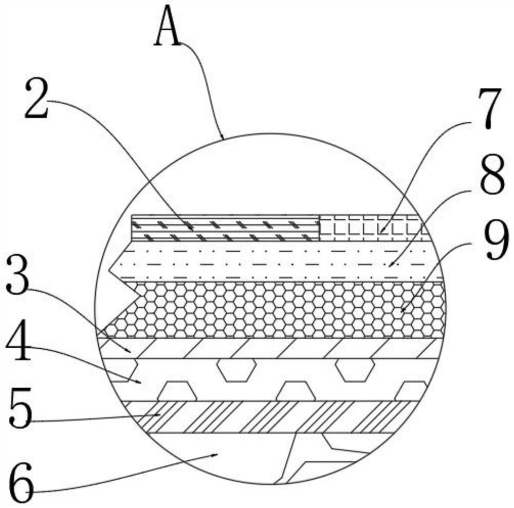
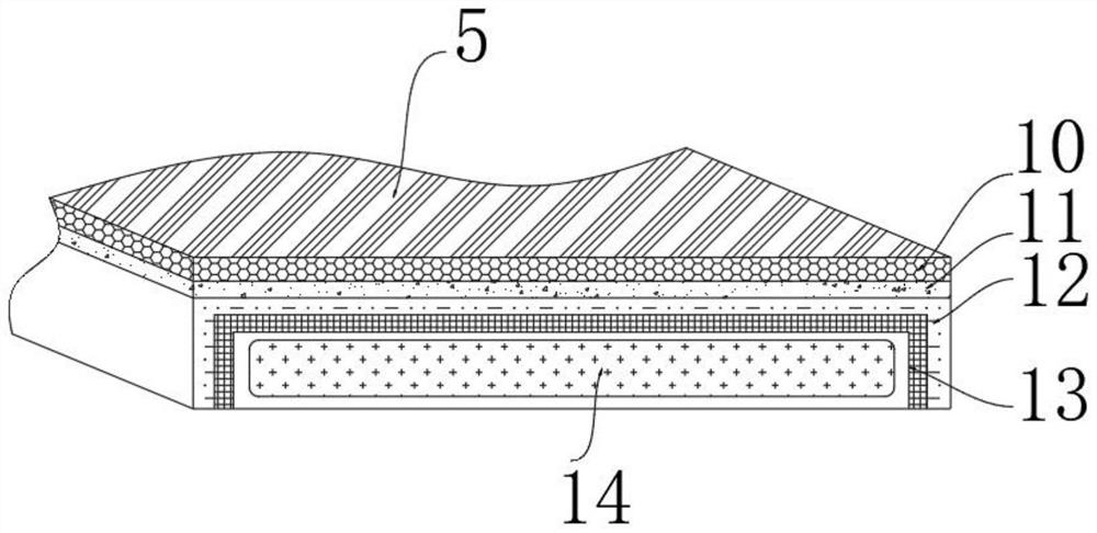
[0031] Such as Figure 1-6 As shown, a roadbed structure at the head of a bridge includes: a roadbed main body 1, and a composite protective cushion layer 5 arranged inside the roadbed main body 1; a bearing surface layer 7, which is arranged on the upper surface of the roadbed main body 1, and The two ends of the bearing surface layer 7 are provided with curb bonding parts 2; the stone cushion layer 6 is arranged directly below the composite protective cushion layer 5, and the outer surface of the stone cushion layer 6 is provided with a stone wrap protection layer 17; The concrete cushion 9 is arranged in the middle of the bearing surface 7 and the stone cushion 6, and the lower end surface of the concrete cushion 9 is provided with a dense cushion 3.
[0032] In the...
PUM
 Abstract
Description
Claims
Application Information