Cooling system for vehicle

A cooling system and vehicle technology, applied in liquid cooling, engine cooling, heating/cooling equipment, etc., can solve problems such as power economy decline, cooling system balance water temperature is low, and system degassing is difficult, so as to reduce emission pollution substances, increase the rate of temperature rise, and high degassing efficiency

Inactive Publication Date: 2020-12-04
YIBIN COWIN AUTO CO LTD
View PDF4 Cites 3 Cited by
  • Summary
  • Abstract
  • Description
  • Claims
  • Application Information

AI Technical Summary

Problems solved by technology

At present, there are more or less the following problems in the cooling system of existing fuel vehicles: the system is difficult to degas, and the manual filling time is longer during after-sales maintenance, especially the semi-closed structure cooling system; the cold start time of the engine is longer, which increases fuel consumption and Emission of pollutants; in the non-hot season environment, under a certain load condition, the equilibrium water temperature of the cooling system is low, resulting in a decline in the power economy of the vehicle; in the warm season environment, under severe working conditions, the equilibrium water temperature of the cooling system is high Even call the police, the deterioration of vehicle emissions has intensified, and the power economy has dropped significantly

Method used


Image

  • Cooling system for vehicle

Examples


Embodiment Construction

[0026] The specific implementation of the present invention will be described in further detail below by describing the embodiments with reference to the accompanying drawings, so as to help those skilled in the art have a more complete, accurate and in-depth understanding of the inventive concepts and technical solutions of the present invention.

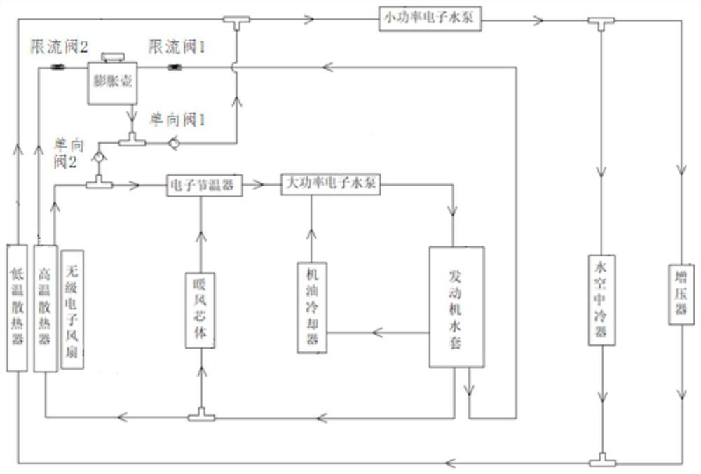
[0027] figure 1 The structural diagram of the vehicle cooling system provided by the embodiment of the present invention, for the convenience of description, only shows the parts related to the embodiment of the present invention.

[0028] The system includes:

[0029] High temperature cooling circuit and low temperature cooling circuit, wherein;

[0030] The high-temperature cooling circuit includes: the engine water jacket, the water outlet 1 of the engine water jacket are respectively connected to the high-temperature radiator and the warm air core through the three-way valve, and the high-temperature radiator and the warm air ...


PUM


Abstract

The invention discloses a cooling system for a vehicle. The cooling system for the vehicle comprises a high-temperature cooling loop and a low-temperature cooling loop, wherein the high-temperature cooling loop comprises an engine water jacket; a water outlet 1 of the engine water jacket is connected with a high-temperature heat radiator and a warm air core body; the high-temperature heat radiatorand the warm air core body are connected with two water inlets of an electronic thermostat; a water outlet of the electronic thermostat is connected with an inlet of a high-power electronic water pump. a water outlet of the high-power electronic water pump is connected with a water inlet of the engine water jacket; a water outlet 2 of the engine water jacket is connected with the other water inlet of the high-power electronic water pump through an engine oil cooler; a low-temperature heat dissipation loop comprises a low-power electronic water pump; a water outlet of the low-power electronicwater pump is connected with water inlets of a water-air intercooler and a turbocharger; water outlets of the water-air intercooler and the turbocharger are connected with a water inlet of a low-temperature heat radiator; and a water outlet of the low-temperature heat radiator is connected with a water inlet of the low-power electronic water pump. The cooling system for the vehicle is beneficial for increasing the temperature rise rate of an engine and reducing the pollutant emission.

Description

technical field [0001] The invention belongs to the technical field of vehicle cooling, and more specifically, the invention relates to a vehicle cooling system. Background technique [0002] As modern automotive engines adopt more compact designs and greater power per unit volume, the degree of strengthening is getting higher and higher, and the heat generated by the engine has also increased significantly. At present, all enhanced engines are faced with how to solve the cooling and heat balance problems of high power density engines. While meeting the continuously increasing power output, they must also have good economy, and the increasingly stringent emission standards have also put forward requirements on the cooling system. new requirements. [0003] The design of modern engine cooling systems has fully considered warm-up, cooling efficiency, exhaust emission control, fuel utilization, and interior heating. The working performance of the cooling system directly affec...

Claims


Application Information

Patent Timeline
Patent Type & Authority Applications(China)
IPC IPC(8): F01P3/20F01P3/02F01P5/10F01P5/02F01P11/02F01P11/00F01P7/16F01M5/00F02B29/04B60H1/04
CPCB60H1/04F01M5/002F01P3/02F01P3/20F01P5/02F01P5/10F01P7/165F01P11/00F01P11/028F02B29/0406Y02T10/12
Inventor 陈磊狄小祥张礼兵肖锋司雪飞
Owner YIBIN COWIN AUTO CO LTD
Why Eureka
Try Eureka