Overflow protection device for induction cooker

A technology for overflow protection and induction cooker, applied in the field of kitchen supplies, can solve problems such as hidden dangers, fires, and inability to leave, and achieve the effects of protecting safety, ensuring safe use, and avoiding water residues

Active Publication Date: 2020-12-04
连云港霍兹节能厨房设备有限公司
View PDF6 Cites 0 Cited by
  • Summary
  • Abstract
  • Description
  • Claims
  • Application Information

AI Technical Summary

Problems solved by technology

[0002] The principle of the induction cooker is the phenomenon of electromagnetic induction, that is, the alternating current is used to pass through the coil to generate an alternating magnetic field with a constantly changing direction. Eddy currents will appear inside the conductor in the alternating magnetic field, which is the eddy electric field that drives the current-carrying in the conductor. The Joule heating effect of the eddy current causes the conductor to heat up, thereby realizing heating. However, since the induction cooker works by electricity, there are often some safety hazards
[0003] When the current induction cooker is in use, water often boils and overflows. Since the induction cooker is driven by electricity, once the inside of the induction cooker encounters water, it will cause the induction cooker to burn, affect the use of the induction cooker, and may even cause a fire. , there are major safety hazards, and it is easy to cause property loss, so you can't leave during use. However, in actual use, you often leave for a short period of time to deal with other things, resulting in the inability to take care of the induction cooker in time.

Method used


Image

  • Overflow protection device for induction cooker
  • Overflow protection device for induction cooker
  • Overflow protection device for induction cooker

Examples


Embodiment Construction

[0019] The technical solutions in the embodiments of the present invention will be clearly and completely described below with reference to the accompanying drawings in the embodiments of the present invention. Obviously, the described embodiments are only a part of the embodiments of the present invention, rather than all the embodiments. Based on the embodiments of the present invention, all other embodiments obtained by those of ordinary skill in the art without creative efforts shall fall within the protection scope of the present invention.

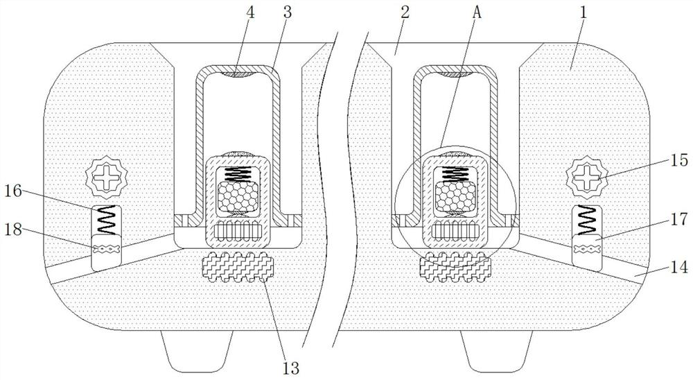
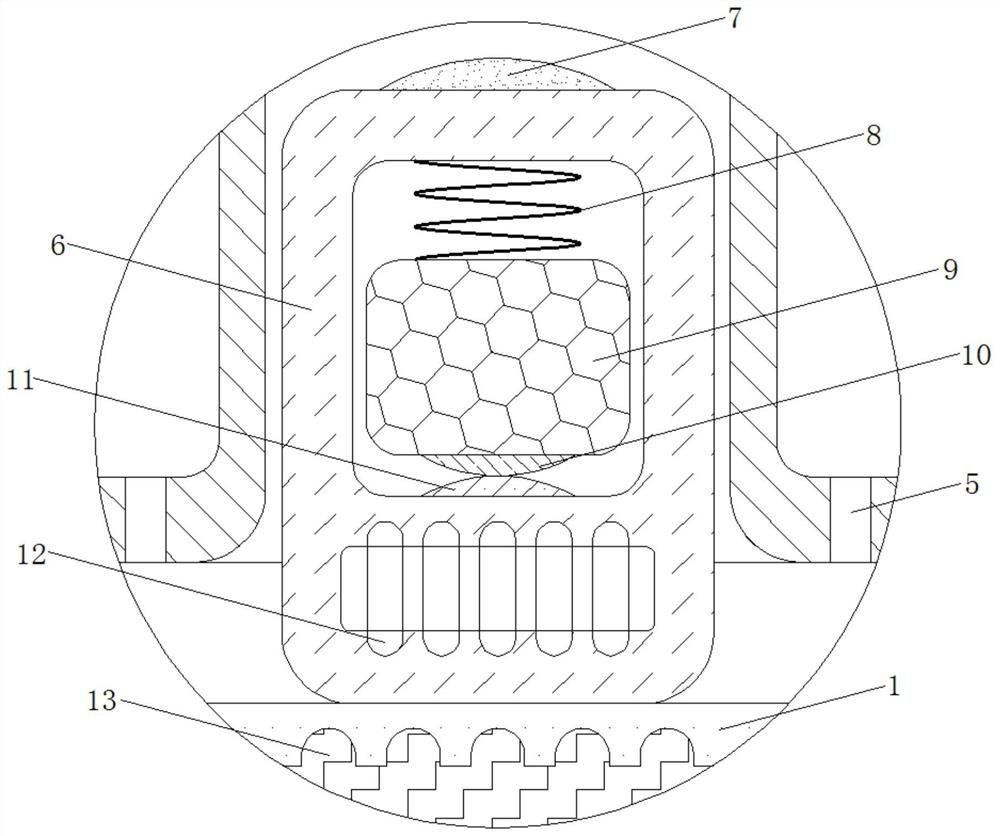
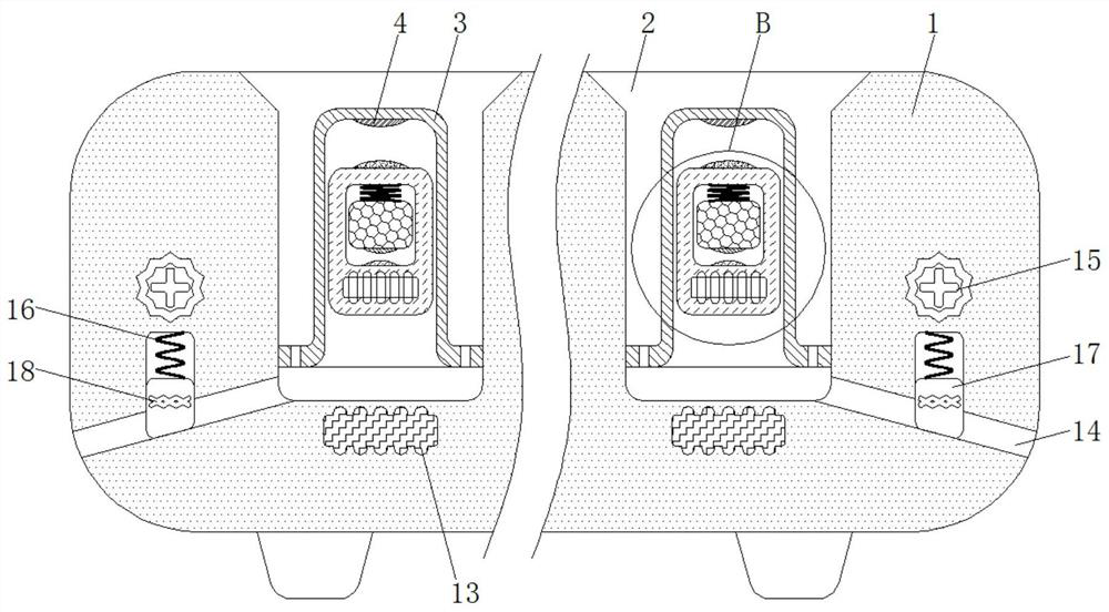
[0020] see Figure 1-4 , an overflow protection device for an induction cooker, comprising a furnace body 1, the furnace body 1 is made of a hard and high-strength material and the furnace body 1 does not have electrical conductivity and magnetic permeability, the furnace body 1 plays the role of fixing various components, and the water inlet The shape of 2 is annular and the depth of the water inlet 2 is less than the height of the ...


PUM


Abstract

The invention provides an overflow protection device for an induction cooker, and relates to the technical field of kitchen supplies. The overflow protection device comprises a cooker body, and a water inlet is formed in the top of the cooker body; a retaining ring is fixedly connected with the inner wall of the cooker body, and an electric contact I is fixedly connected with the inner top wall ofthe retaining ring; and water leakage holes uniformly distributed are formed in the bottom of the retaining ring. According to the overflow protection device for the induction cooker, through cooperative application of an electric contact III and an electric contact IV, and in the initial state, an electromagnet I and an electromagnet II are in a power-off state, and in case of overflow of the induction cooker, a floating block is moved upwards under the buoyancy effect of water, so that the electric contact I and an electric contact II are electrically connected; and the electromagnet I andthe electromagnet II are powered on. At the moment, the floating block is moved downwards under the magnetic attraction effect of the electromagnet I and the electromagnet II, and a conductive block is moved upwards under the effect of centrifugal force, so that the electric contact III and the electric contact IV are separated; thus, the effect of disconnecting a circuit of the induction cooker is achieved, and the circuit is effectively cut off; and the safety of the induction cooker is protected.

Description

technical field [0001] The invention relates to the technical field of kitchen appliances, in particular to an overflow protection device for an induction cooker. Background technique [0002] The principle of the induction cooker is the phenomenon of electromagnetic induction, that is, the alternating current is used to pass through the coil to generate an alternating magnetic field whose direction is constantly changing. Eddy current will appear inside the conductor in the alternating magnetic field, which is the eddy electric field that pushes the current in the conductor. The Joule heating effect of the eddy current causes the conductor to heat up due to the movement of the sub-electrons, thereby achieving heating. However, since the induction cooker works by electricity, there are often some potential safety hazards. [0003] When the current induction cooker is in use, water often boils and overflows. Since the induction cooker is driven by electricity, once the interi...

Claims


Application Information

Patent Timeline
Patent Type & Authority Applications(China)
IPC IPC(8): F24C7/06F24C7/08F24C15/14
CPCF24C7/067F24C7/082F24C15/14
Inventor 胡淑倩
Owner 连云港霍兹节能厨房设备有限公司
Why Eureka
Try Eureka