Water overflow protection device for induction cooker

A water overflow protection and induction cooker technology, which is applied in the field of kitchen supplies, can solve problems such as hidden safety hazards, fires, and inability to leave, and achieve the effects of protecting safety, ensuring safe use, and avoiding water residue

Active Publication Date: 2021-08-06
连云港霍兹节能厨房设备有限公司
View PDF7 Cites 0 Cited by
  • Summary
  • Abstract
  • Description
  • Claims
  • Application Information

AI Technical Summary

Problems solved by technology

[0002] The principle of the induction cooker is the phenomenon of electromagnetic induction, that is, the alternating current is used to pass through the coil to generate an alternating magnetic field with a constantly changing direction. Eddy currents will appear inside the conductor in the alternating magnetic field, which is the eddy electric field that drives the current-carrying in the conductor. The Joule heating effect of the eddy current causes the conductor to heat up, thereby realizing heating. However, since the induction cooker works by electricity, there are often some safety hazards
[0003] When the current induction cooker is in use, water often boils and overflows. Since the induction cooker is driven by electricity, once the inside of the induction cooker encounters water, it will cause the induction cooker to burn, affect the use of the induction cooker, and may even cause a fire. , there are major safety hazards, and it is easy to cause property loss, so you can't leave during use. However, in actual use, you often leave for a short period of time to deal with other things, resulting in the inability to take care of the induction cooker in time.

Method used


Image

  • Water overflow protection device for induction cooker
  • Water overflow protection device for induction cooker
  • Water overflow protection device for induction cooker

Examples


Embodiment Construction

[0019] The following will clearly and completely describe the technical solutions in the embodiments of the present invention with reference to the accompanying drawings in the embodiments of the present invention. Obviously, the described embodiments are only some, not all, embodiments of the present invention. Based on the embodiments of the present invention, all other embodiments obtained by persons of ordinary skill in the art without making creative efforts belong to the protection scope of the present invention.

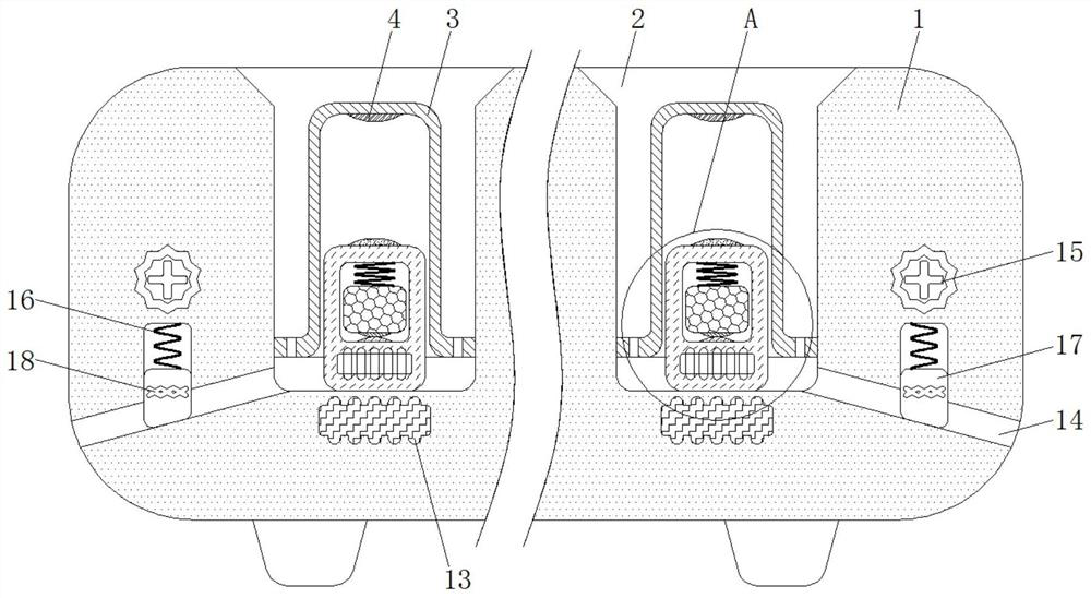
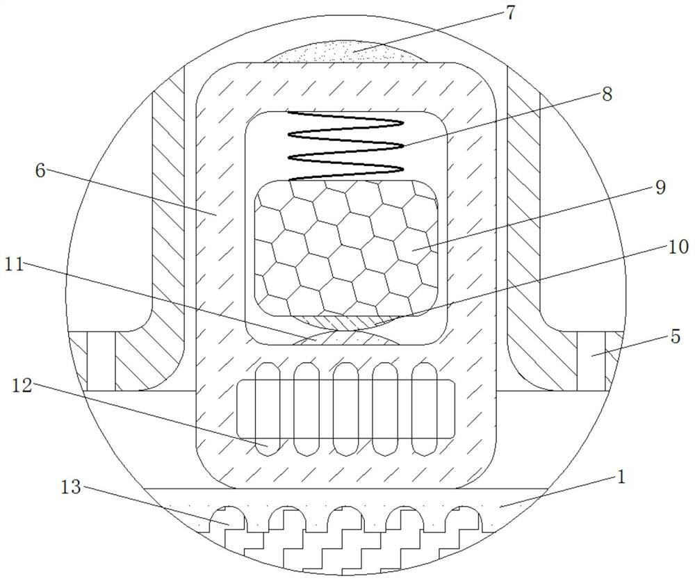
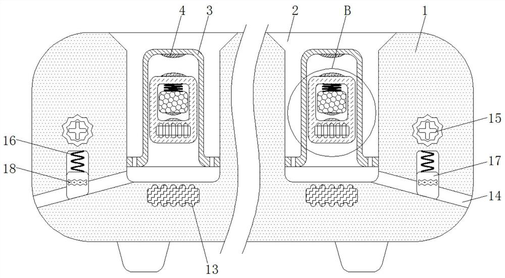
[0020] see Figure 1-4 , a water overflow protection device for an electromagnetic oven, including a furnace body 1, the material of the furnace body 1 is a hard high-strength material and the furnace body 1 does not have electrical conductivity and magnetic conductivity, the furnace body 1 plays the role of fixing various parts, and the water inlet The shape of 2 is circular and the depth of water inlet 2 is less than the height of furnace body 1. Water inlet...


PUM


Abstract

A water overflow protection device for an induction cooker, which relates to the technical field of kitchen supplies. A water overflow protection device for an induction cooker includes a furnace body. A water inlet is provided on the top of the furnace body. The inner top wall is fixedly connected with an electric contact one, and the bottom of the limit ring is provided with evenly distributed water leakage ports. The water overflow protection device for the induction cooker is used in conjunction with the electric contact three and the electric contact four. In the initial state, the electromagnetic one and the electromagnetic two are in the power-off state. When the induction cooker overflows, the floating block will be in the buoyancy of the water. Move upward under the action, so that the electric contact 1 and the electric contact 2 are electrically connected, and the electromagnetic 1 and the electromagnetic 2 are energized. At this time, the floating block will move downward under the magnetic attraction of the electromagnetic 1 and the electromagnetic 2. At this time, the conductive block It will move upward under the action of centrifugal force, so that the electric contact three and electric contact four are separated, thereby achieving the effect of disconnecting the circuit of the induction cooker, effectively cutting off the circuit, and protecting the safety of the induction cooker.

Description

technical field [0001] The invention relates to the technical field of kitchen supplies, in particular to a water overflow protection device for an electromagnetic oven. Background technique [0002] The principle of the induction cooker is the phenomenon of electromagnetic induction, that is, the alternating current is used to pass through the coil to generate an alternating magnetic field with a constantly changing direction. Eddy currents will appear inside the conductor in the alternating magnetic field, which is the eddy electric field that drives the current-carrying in the conductor. The Joule heating effect of the eddy current causes the conductor to heat up, thereby realizing heating. However, since the induction cooker works by electricity, there are often some safety hazards. [0003] When the current induction cooker is in use, water often boils and overflows. Since the induction cooker is driven by electricity, once the inside of the induction cooker encounters ...

Claims


Application Information

Patent Timeline
Patent Type & Authority Patents(China)
IPC IPC(8): F24C7/06F24C7/08F24C15/14
CPCF24C7/067F24C7/082F24C15/14
Inventor 胡淑倩
Owner 连云港霍兹节能厨房设备有限公司
Why Eureka
Try Eureka