
Efficient drying device for tea processing

A drying device and high-efficiency technology, applied in the direction of tea drying, drying, drying machine, etc., can solve the problems of poor gas fluidity, output, unfavorable tea drying, etc., to improve work efficiency, high work speed, and high work efficiency Effect

Inactive Publication Date: 2020-12-04
舒城桢玥绿丰园农民专业合作社
View PDF1 Cites 2 Cited by
  • Summary
  • Abstract
  • Description
  • Claims
  • Application Information

AI Technical Summary

Problems solved by technology

However, when the device is in use, the fluidity of the gas drying the tea leaves is poor, which affects the uniform heating of the tea leaves, and the dried tea leaves cannot be automatically output, which is not conducive to the drying of large quantities of tea leaves.

Method used


Image

  • Efficient drying device for tea processing
  • Efficient drying device for tea processing
  • Efficient drying device for tea processing

Examples


Embodiment 1

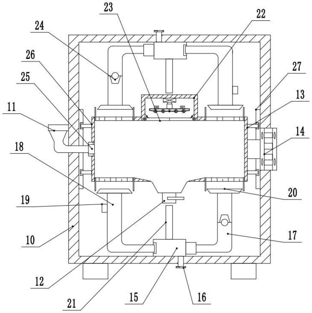
[0020] see Figure 1-2 , a high-efficiency drying device for tea processing, comprising a box body 10, a feed port 11, and a material outlet port 12; the left and right sides of the bottom of the box body 10 are fixedly supported by brackets, and the inner center of the box body 10 is provided with a A set of horizontal drying cylinders 13, the bottom middle of the drying cylinder 13 is provided with a discharge port 12 downward, and the middle part of the left side wall of the drying cylinder 13 is connected to the outside through the rotating communication valve 25. The end of the L-shaped structure extends to The feed port 11 on the outside of the left side wall of the box body 10, and the top of the feed port 11 is provided with a trumpet-shaped structure that facilitates feeding. The left and right side walls of the drying cylinder 13 are fixed symmetrically and fixedly installed with a rotating track 26. The rotating track 26 is rotatably connected to the chute opened in...

Embodiment 2

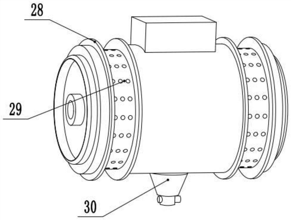
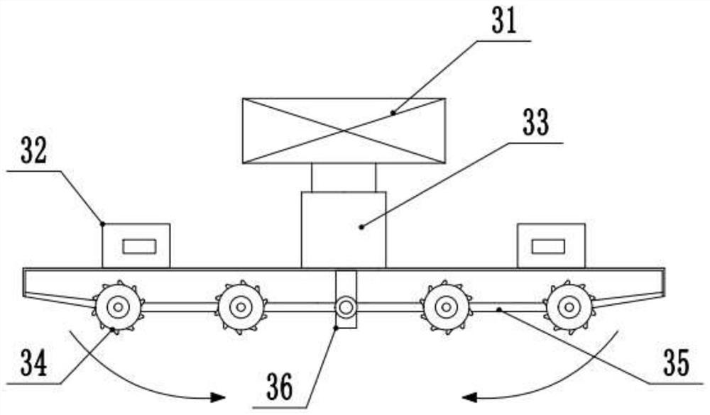
[0022] see image 3, on the basis of the first embodiment, the inside of the drying cylinder 13 at the top of the discharge port 12 is connected downward with a funnel-shaped feeding channel 30, and the feeding channel 30 is convenient for the tea leaves inside the drying cylinder 13 to pass through. It flows into the feed channel 30 under the action of gravity. A set of discharge cavities 22 are fixedly installed in the middle of the outer top of the drying cylinder 13, and a set of elevators 31 are fixedly installed on the inner top of the discharge cavity 22. The bottom of 33 is fixedly installed with a set of mounting frames, and the tops of the left and right sides of the mounting frame are fixedly provided with two sets of driving devices 32 with opposite directions of rotation. , The feeding rollers 34 are connected in rotation by the transmission belt 35, and the left and right feeding rollers 34 are separated from each other by the connecting plate 36 fixed at the mi...


PUM


Abstract

The invention relates to the technical field of tea processing, and discloses an efficient drying device for tea processing. The efficient drying device comprises a box body, a feeding opening and a discharging opening; a circle of grooves is inwards formed in each of the left curved side face and the right curved side face of a drying cylinder, and a plurality of air holes are evenly formed inside the grooves; the middle parts of the upper side wall and the lower side wall of the box body are fixedly provided with a set of air heaters with opposite output ends correspondingly, the right end of the air heater at the lower side and the left end of the air heater at the upper side communicate with a set of air conveying pipes of which the end parts extend to the position right below the grooves at the right side and the position right above the grooves at the left side respectively, and the left end of the air heater at the lower side and the right end of the air heater at the upper sidecommunicate with a set of return pipes of which the end parts extend to the position right below the grooves at the left side and the position right above the grooves at the right side respectively;and a discharging cavity is fixedly arranged in the middle part of the outer top of the drying cylinder. The efficient drying device for tea processing has the advantages that air circularly flows andfor heating, tea leaves are uniformly overturned and heated, and automatic discharging is achieved, so that overall work is efficient.

Description

technical field [0001] The invention relates to the technical field of tea processing, in particular to a high-efficiency drying device for tea processing. Background technique [0002] Drying is an important process in tea making. Its main purpose is to remove all the water inside and outside the tea leaves, and at the same time achieve the purpose of setting the tea leaves and resisting oxidation. When using some existing tea drying devices, by placing the tea leaves in the The inside of the device is then dried by the box filling device inside the device. [0003] Chinese Patent (Announcement No.: CN 210180068 U, Announcement Date: 2020.03.24) discloses a high-efficiency drying device for tea processing, including a base, two side plates, two supporting springs, a box body, a first motor, a third A gear, a partition, two rotating rods, a second gear, a placing box and a vibration mechanism, so that when the device is in use, the driving wheel can be driven to rotate by t...

Claims


Application Information

Patent Timeline
Patent Type & Authority Applications(China)
IPC IPC(8): F26B11/04F26B21/04F26B25/04F26B25/16A23F3/06
CPCA23F3/06F26B11/044F26B21/001F26B21/004F26B21/04F26B25/04F26B25/16F26B2200/20
Inventor 郭正李桢谢文月李年东
Owner 舒城桢玥绿丰园农民专业合作社
Features
  • Generate Ideas
  • Intellectual Property
  • Life Sciences
  • Materials
  • Tech Scout
  • Unparalleled Data Quality
  • Higher Quality Content
  • 60% Fewer Hallucinations
Learn More