Steel rail damage detection system and method and computer equipment

A technology of computer equipment and detection system, which is applied in the direction of railway auxiliary equipment, measuring devices, railway vehicle shape measuring devices, etc., can solve problems such as unfavorable running of flaw detection vehicles, missed detection of rail damage, weakening of ultrasonic signal strength, etc. The effect of replacing manual hand-push testing equipment, reducing labor costs, and ensuring quality and safety

Pending Publication Date: 2020-12-04
CHINA ACADEMY OF RAILWAY SCI CORP LTD +3
View PDF0 Cites 1 Cited by
  • Summary
  • Abstract
  • Description
  • Claims
  • Application Information

AI Technical Summary

Problems solved by technology

[0012] However, figure 2 and image 3 The technical method shown is to measure the centering deviation, and then use the servo motor or drive hydraulic system to calibrate the deviation of the probe wheel. Although the problem of centering deviation has been largely solved, the deviation has already occurred at this time, and the ultrasonic The signal has been weakened or even disappeared due to the centering deviation of the probe wheel, which may lead to missed detection of rail damage
Figure 4 The technology shown can meet the centering requirements when running at low speed, but as the running speed increases, the lateral stretching force of the tracking cylinder increases greatly. Excessive lateral force is very unfavorable for the safe running of the flaw detection vehicle and cannot be realized. Mechanical Alignment of Flaw Detection Car at 80km / h Speed

Method used


Image

  • Steel rail damage detection system and method and computer equipment
  • Steel rail damage detection system and method and computer equipment
  • Steel rail damage detection system and method and computer equipment

Examples


Embodiment Construction

[0036] In order to make the purpose, technical solutions, and advantages of the embodiments of the present application clearer, the embodiments of the present application will be further described in detail below in conjunction with the accompanying drawings. Here, the exemplary embodiments of the application and their descriptions are used to explain the application, but not to limit the application.

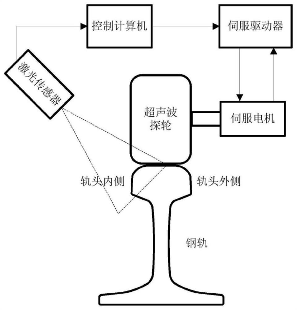
[0037] The embodiment of the present application provides a detection system for rail damage, such as Figure 5 As shown, the detection system includes:

[0038] The centering probe wheel includes at least two calibration crystals, one of the at least two calibration crystals transmits the first ultrasonic signal, and each calibration crystal receives the first rail bottom echo signal of the steel rail for the first ultrasonic signal, and at least two The connecting line of the calibration wafers is perpendicular to the extending direction of the steel rail.

[0039] It shoul...


PUM


Abstract

The invention discloses a steel rail damage detection system and method and computer equipment, wherein the detection system comprises that a first ultrasonic signal is transmitted to one of at leasttwo calibration wafers of a central detection wheel, and each calibration wafer receives a first rail bottom echo signal; each detection wafer in at least two detection wafers of the detection wheel emits a second ultrasonic signal and receives a second rail bottom echo signal, and the echo signal intensity of the second rail bottom echo signal is determined; the computer equipment is connected with a detecting detection wheel and a centering detection wheel and is used for determining a deviation value and a deviation direction of the centering detection wheel according to the first rail bottom echo signal, determining a signal compensation value of each detection wafer, and determining whether a steel rail at the second rail bottom echo signal acquisition position is damaged or not according to the signal compensation value of each detection wafer and the echo signal intensity of the corresponding wafer. The situation that a flaw detection vehicle running at the speed of 80 km/h leaks detection of the damage of the steel rail can be reduced.

Description

technical field [0001] The present application relates to the technical field of non-destructive testing, in particular to a rail damage detection system, method and computer equipment. Background technique [0002] This section is intended to provide a background or context to embodiments of the invention that are recited in the claims. The descriptions herein are not admitted to be prior art by inclusion in this section. [0003] The use of large-scale rail flaw detection vehicles to carry out rapid and periodic inspections of in-service lines is playing an increasingly important role in ensuring line safety. The detection capability of the rail flaw detection vehicle largely depends on the alignment of the ultrasonic wheel probe (hereinafter referred to as the probe wheel) during fast operation. When the rail flaw detection vehicle cannot ensure the lateral alignment of the probe wheel and the rail, the ultrasonic signal cannot effectively enter the In the designated ar...

Claims


Application Information

Patent Timeline
Patent Type & Authority Applications(China)
IPC IPC(8): G01N29/04G01N29/265B61K9/10
CPCB61K9/10G01N29/04G01N29/265G01N2291/0234G01N2291/2623
Inventor 马运忠熊龙辉张玉华李培钟艳春
Owner CHINA ACADEMY OF RAILWAY SCI CORP LTD
Why Eureka
Try Eureka