
Millimeter wave multi-feed-source compact range test system

A test system, millimeter wave technology, applied in the direction of the antenna radiation pattern, etc., can solve the problem of not having a radio frequency conduction interface, and achieve the effect of improving work efficiency

Active Publication Date: 2020-12-04
北京中测国宇科技有限公司
View PDF32 Cites 11 Cited by
  • Summary
  • Abstract
  • Description
  • Claims
  • Application Information

AI Technical Summary

Problems solved by technology

The radio frequency unit of the mmWave base station and other mmWave devices do not have the RF conduction interface traditionally used for cable testing, and can only be measured by the air interface OTA method

Method used


Image

  • Millimeter wave multi-feed-source compact range test system
  • Millimeter wave multi-feed-source compact range test system
  • Millimeter wave multi-feed-source compact range test system

Examples


Embodiment Construction

[0019] The present invention will be further described below in conjunction with the accompanying drawings and specific embodiments.

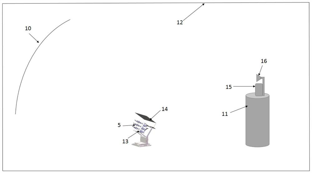
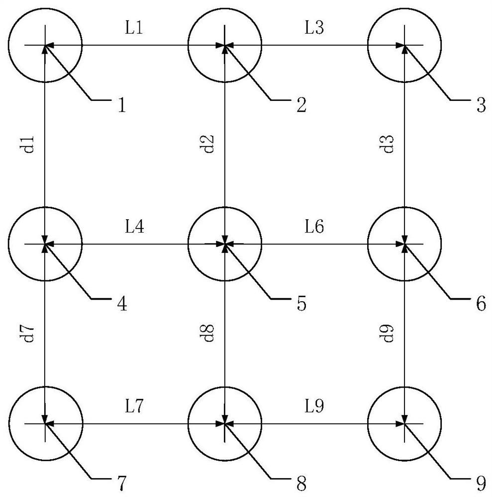
[0020] Such as Figure 1-4 As shown, a millimeter-wave multi-feed source compact field test system includes nine millimeter-wave band feed sources 1, 2, 3, 4, 5, 6, 7, 8, 9, a reflector 10, a turntable system 11, A direct drain baffle 14, an antenna to be tested 15 and a reference antenna 16, the test system is located in the microwave anechoic chamber 12, wherein the fifth feed source 5 is located at the focal point of the reflection surface, and the first feed source 1 and the fifth feed source 5 are horizontal The distance is L1, the vertical distance is d1, the horizontal distance between the second feed source 2 and the fifth feed source is L2, and the vertical distance is d2, the horizontal distance between the third feed source 3 and the fifth feed source 5 is L3, and the vertical distance is d3, The horizontal distance between the four...


PUM


Abstract

The invention relates to a millimeter wave multi-feed-source compact range testing system which comprises nine millimeter wave feed sources (1, 2, 3, 4, 5, 6, 7, 8 and 9) at different positions, a reflecting surface (10), a turntable system (11), a direct leakage baffle (14), an antenna to be tested (15) and a reference antenna (16). The phase center of the central feed source is located at the focus of the reflecting surface, the other eight feed sources are located near the focus, and the relative position of each feed source and the central feed source is determined according to the position of a dead zone, the deflection angle of the dead zone and the geometric dimension of the reflecting surface. When millimeter-wave antenna measurement is carried out, directional diagram testing canbe carried out on an antenna at multiple angles at the same time by rapidly switching the working states and polarization modes of different feed sources, and the testing efficiency of the millimeter-wave antenna is greatly improved.

Description

technical field [0001] The invention relates to the technical field of a compact field test system, in particular to a millimeter wave multi-feed source compact field test system. Background technique [0002] At present, 5G is about to enter the commercial stage, but before the official commercial use, there are still many problems to be solved urgently, and various mobile communication manufacturers are still conducting related 5G technology tests. As one of the key technologies of 5G, millimeter wave technology has many unresolved complex problems. Due to the high operating frequency and large bandwidth of millimeter wave equipment, it is gradually developing towards the high integration of circuits and chip components. The radio frequency unit of the millimeter-wave base station and other millimeter-wave equipment do not have the RF conduction interface that traditionally uses cables for testing, and can only be measured using the air interface OTA method. Therefore, 5...

Claims


Application Information

Patent Timeline
IPC IPC(8): G01R29/10
CPCG01R29/10Y02D30/70
Inventor 宁宗贺陈海波
Owner 北京中测国宇科技有限公司
Learn More