Metal plate bending equipment for machining of mechanical equipment

A technology of mechanical equipment and metal plates, which is applied in the field of metal plate bending equipment for mechanical equipment processing, can solve the problems of metal plate side deformation and cumbersome process, etc., and achieve increased bending efficiency, fast and convenient use, and simple and reasonable structure Effect

Inactive Publication Date: 2020-12-08
刘素勤
View PDF0 Cites 1 Cited by
  • Summary
  • Abstract
  • Description
  • Claims
  • Application Information

AI Technical Summary

Problems solved by technology

[0003] Sheet metal parts are commonly used in construction sites and various mechanical engineering. In actual use, sheet metal parts will be processed to different degrees according to different conditions, such as cutting, polishing, bending and other processes, among which bending The process is inseparable from the use of bending equipment. Bending, as the name implies, is to bend the original metal sheet in a certain degree of arc shape. Traditional bending is done by applying a length opposite to the length of the metal sheet on both sides. However, this process is likely to cause deformation of the side of the metal plate, and subsequent processes such as cutting or polishing are required. The process is cumbersome

Method used


Image

  • Metal plate bending equipment for machining of mechanical equipment
  • Metal plate bending equipment for machining of mechanical equipment
  • Metal plate bending equipment for machining of mechanical equipment

Examples


Embodiment Construction

[0024] Below, in conjunction with accompanying drawing and specific embodiment, the invention is further described:

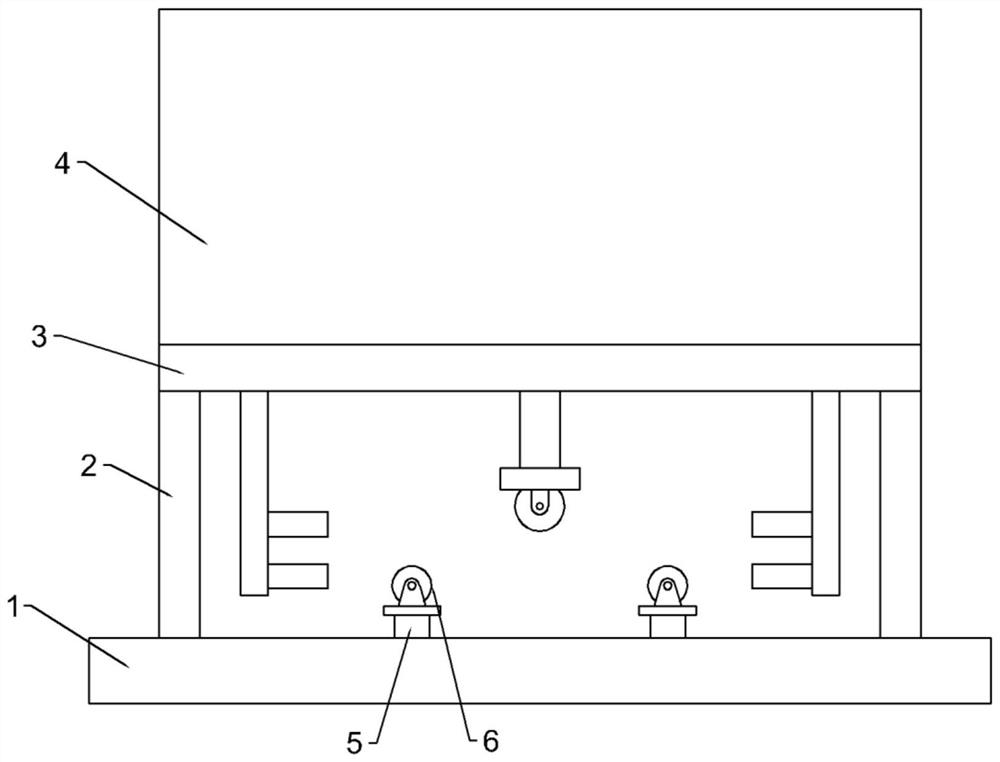
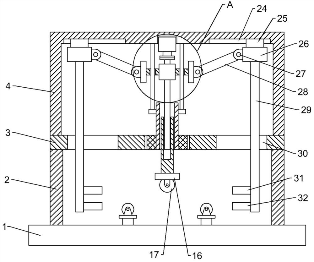
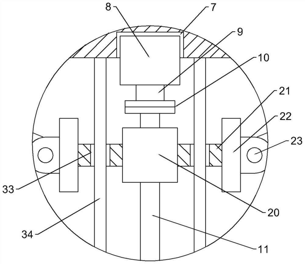
[0025] see Figure 1-5 According to an embodiment of the present invention, a metal plate bending equipment for mechanical equipment processing includes a bottom plate 1, and support rods 2 are fixedly installed on the top four corners of the bottom plate 1, and the support rods 2 are perpendicular to the bottom plate 1, and the support rods 2 The top end of the top plate 3 is fixedly installed with a top plate 3, and the top of the top plate 3 is fixedly installed with a cover 4, and the center of the inner top wall of the cover 4 is provided with a mounting groove 7, and a driving motor 8 is installed in the mounting groove 7, and the driving motor 8 The bottom end of the motor shaft 9 is installed, and the bottom end of the motor shaft 9 is connected with a screw rod 11 through a coupling 10. The screw rod 11 is arranged in line with the motor shaft 9, and t...


PUM


Abstract

The invention discloses metal plate bending equipment for mechanical equipment machining. The metal plate bending equipment comprises a bottom plate, supporting rods, a top plate and a housing, wherein a mounting groove is formed in the center of the inner top wall of the housing, a driving motor is embedded in the mounting groove, a motor shaft is mounted at the bottom end of the driving motor, and a lead screw is connected to the bottom end of the motor shaft through a coupler. The metal plate bending equipment has the beneficial effects that when an inserting rod extends, a pressing rollerarranged at the bottom end of the inserting rod can move towards the bottom plate, and the pressing roller can extrude the middle of a metal plate between two vertical rods, so that the bending function is achieved; when connecting rods move, the connecting rods can drive moving blocks to move through second hinge seats, and the moving blocks can drive the vertical rods to move; and when the inserting rods extend, the vertical rods get close to each other, and force is applied to the two ends of the metal plate, so that it can be guaranteed that the distance between the two ends of the metal plate is effectively controlled, the bending of the metal plate can be assisted, and the bending efficiency is improved.

Description

technical field [0001] The invention relates to the technical field of mechanical equipment processing, in particular to a metal plate bending equipment for mechanical equipment processing. Background technique [0002] There are many kinds of mechanical equipment. When the mechanical equipment is running, some of its parts and even itself can perform different forms of mechanical movement. Mechanical equipment consists of driving device, transmission device, transmission device, working device, braking device, protection device, lubrication system, cooling system and other parts. [0003] Sheet metal parts are commonly used in construction sites and various mechanical engineering. In actual use, sheet metal parts will be processed to different degrees according to different conditions, such as cutting, polishing, bending and other processes, among which bending The process is inseparable from the use of bending equipment. As the name suggests, bending is to bend the origin...

Claims


Application Information

Patent Timeline
Patent Type & Authority Applications(China)
IPC IPC(8): B21D5/01B21D5/00B21D43/00
CPCB21D5/002B21D5/01B21D43/003
Inventor 刘素勤
Owner 刘素勤
Why Eureka
Try Eureka