Mould for manufacturing induction coil and method for manufacturing induction coil

A technology of induction coils and molds, applied in the manufacture of inductors/transformers/magnets, electrical components, circuits, etc., can solve the problems of short circuit and ignition, no mold coil, poor heating effect, etc., to reduce deformation and flexibility High, widely used effect

Pending Publication Date: 2019-09-17
宁波众远新材料科技有限公司
View PDF0 Cites 1 Cited by
  • Summary
  • Abstract
  • Description
  • Claims
  • Application Information

AI Technical Summary

Problems solved by technology

The production of induction coils in the prior art mainly relies on manual production by technicians, and there is no mold for the production of coils. Therefore, even experienced technicians will have the following problems in the production of induction coils:
[0003] 1. The diameter of each turn of the coil cannot be accurately controlled
When the diameter of each turn of the circular coil and conical coil cannot be guaranteed to be accurate, the bar cannot be guaranteed to be in the center of the induction coil when the bar is smelted, so the surface of the bar cannot be guaranteed to be heated evenly
[0004] 2. The turn distance between each turn of the coil cannot be guaranteed to be uniform
The turn distance between the coils cannot be kept uniform, which will also lead to uneven heating of the rod to be heated
If the turn distance is too small, short circuit and sparking will easily occur. If the turn distance is too large, the heating effect will not be good, so the turn distance needs to be precisely controlled.
[0005] 3. The induction coil is easily deformed
Especially when copper and brass are used, the material is relatively soft. During the manual production process, the coil will be deformed due to force, and there will be pits and protrusions.
When the cooling water is passed into the coil, the cooling effect will be weakened if the cooling water is not smooth, and when the cooling water accumulates in the coil, it is easy to cause the coil to be blocked

Method used


Image

  • Mould for manufacturing induction coil and method for manufacturing induction coil
  • Mould for manufacturing induction coil and method for manufacturing induction coil
  • Mould for manufacturing induction coil and method for manufacturing induction coil

Examples


Embodiment 2

[0067] The specific manufacturing process of an induction coil is as follows:

[0068] (1) Design coil

[0069] The induction coil is designed according to the size and shape of the workpiece to be heated, the temperature to be heated, etc. The main parameters are coil shape, coil turns, coil pitch, coil height, coil material, coil inner diameter and outer diameter and other parameters.

[0070] When the workpiece is small, the designed gap between the coil and the workpiece should be about 5mm. When heating a larger workpiece, it is necessary to consider increasing the number of turns of the induction coil while reducing the gap between the workpiece and the induction coil. Three types of coils are given as examples, as shown in Table 1:

[0071] Table 1 Induction coil parameters

[0072]

[0073] After the above parameters are determined, the indicators of the induction coil can be determined.

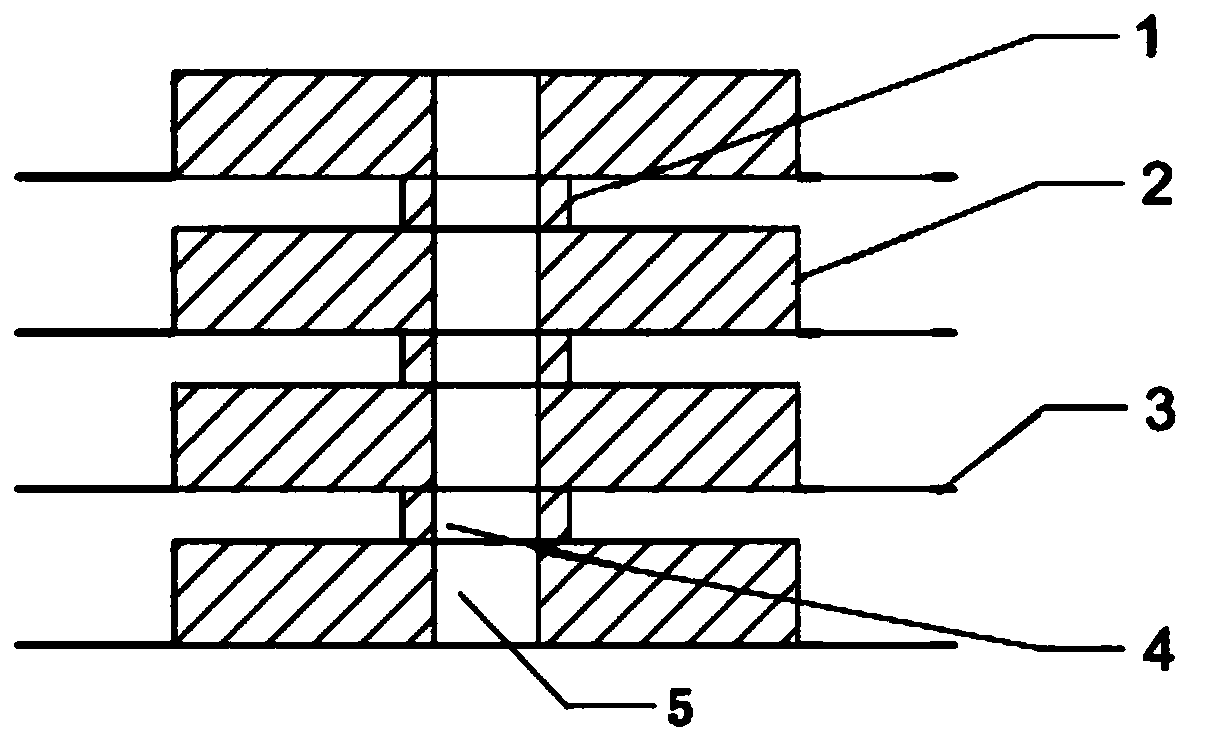
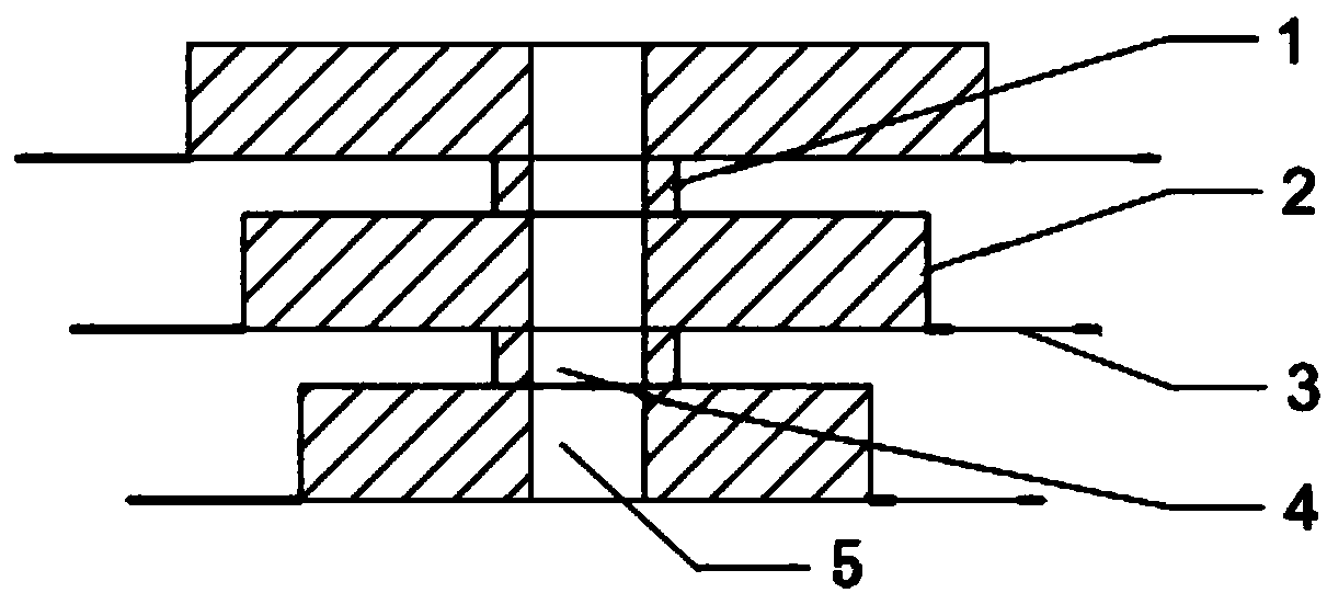
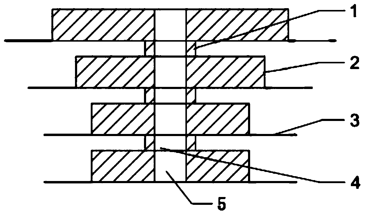
[0074] (2) tire assembly

[0075] According to the coil parameters and ...


PUM

PropertyMeasurementUnit
thicknessaaaaaaaaaa
diameteraaaaaaaaaa
thicknessaaaaaaaaaa

Abstract

A mould for manufacturing an induction coil comprises a plurality of diameter adjusting discs which are sequentially arranged from top to bottom. Stand columns used for adjusting the turn pitch are arranged between the adjacent diameter adjusting discs, and the center points of the diameter adjusting discs and the center points of the stand columns are located on the same axis. According to the invention, based on working condition requirements, different numbers of control modules with different diameters are selected to manufacture the induction coil; the inner diameter of each turn of coil and the turn number of the coils are guaranteed through the diameter adjusting discs; the distance between coils is guaranteed through the stand columns; it is guaranteed that the coils are not deformed by pouring fine sand into the coils; the diameter of each turn of the induction coil prepared through the mould is within the controllable range; and the number of turns can be flexibly changed.

Description

technical field [0001] The invention relates to the field of manufacturing induction coils, and more specifically, to a mold for manufacturing induction coils and a method for making the coils. Background technique [0002] The heating effect of the high-frequency induction coil mainly depends on the working current of the induction coil. In addition, it is also directly related to factors such as the shape, number of turns, and pitch of the induction coil. To make the most effective use of the power of the equipment , It is also very important to design the induction coil reasonably according to the material and shape of the workpiece. The production of induction coils in the prior art mainly relies on manual production by technicians, and there is no mold for the production of coils. Therefore, even experienced technicians will have the following problems in the production of induction coils: [0003] 1. The diameter of each turn of the coil cannot be accurately controlle...

Claims


Application Information

Patent Timeline
Patent Type & Authority Applications(China)
IPC IPC(8): H01F41/071
CPCH01F41/071
Inventor 徐飞鹏励达程文进
Owner 宁波众远新材料科技有限公司
Why Eureka
Try Eureka