
Iron and steel metallurgical furnace

A technology for iron and steel metallurgy and furnace shell, applied in the field of iron and steel metallurgy furnaces, can solve the problems of continuous smelting due to wrong feeding, reduced melting efficiency of long steel bars, damage to refractory layers, etc., and achieves the effect of ensuring normal use, improving melting efficiency and reducing damage.

Pending Publication Date: 2020-12-08
陈祥瑞
View PDF0 Cites 0 Cited by
  • Summary
  • Abstract
  • Description
  • Claims
  • Application Information

AI Technical Summary

Problems solved by technology

[0005] This patent facilitates the recovery of wrongly added materials, solves the defect that continuous smelting cannot be realized due to wrongly added materials, and improves production efficiency; but this patent cannot solve the problem of long steel bars being discharged during the process of recycling iron and steel scrap in iron and steel metallurgical furnaces. The middle is easy to collide with the inner wall of the refractory layer, causing damage to the refractory layer, and the long steel bars tend to lean against the inner wall of the refractory layer, and some of the long steel bars cannot fully contact with the molten iron, resulting in a decrease in the melting efficiency of the long steel bars and easy accumulation of waste; Accordingly, the present invention proposes a steel metallurgical furnace

Method used


Image

  • Iron and steel metallurgical furnace
  • Iron and steel metallurgical furnace
  • Iron and steel metallurgical furnace

Examples


Embodiment approach

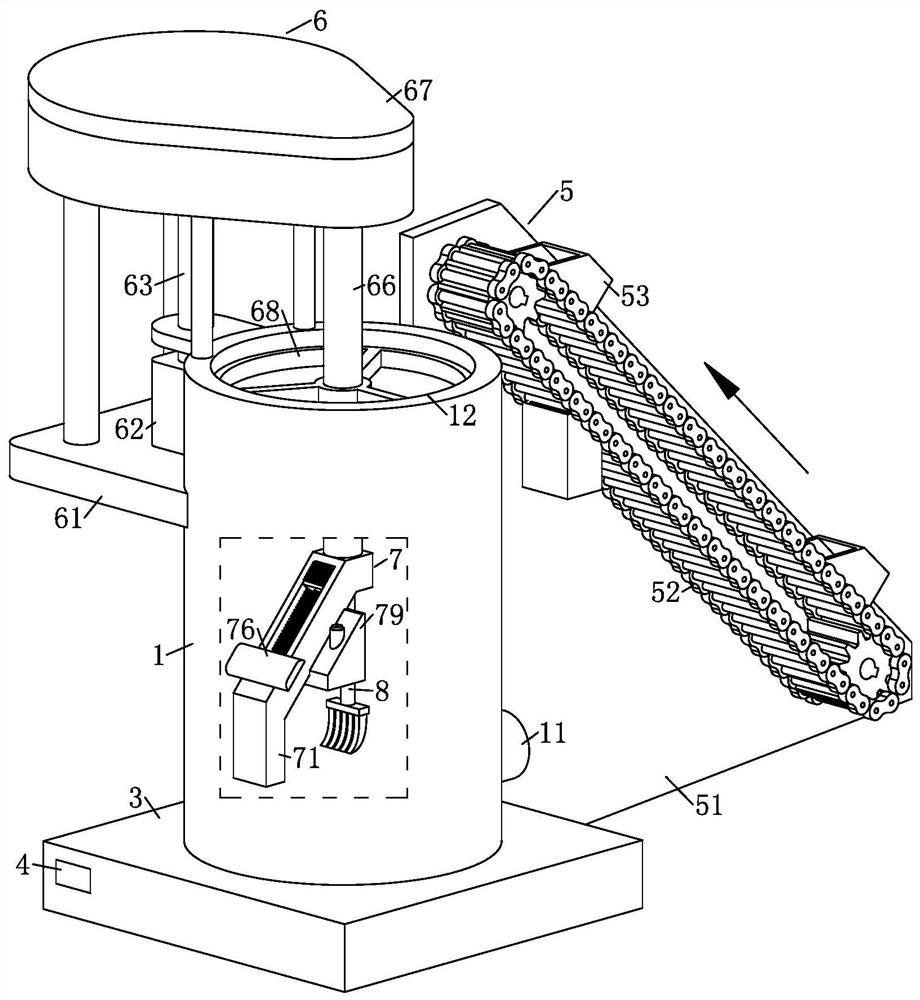
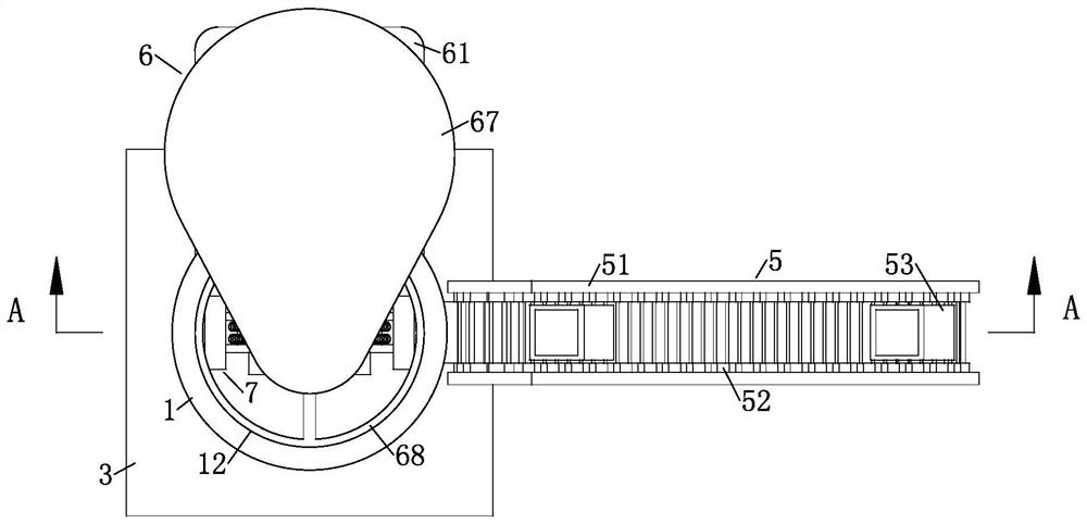
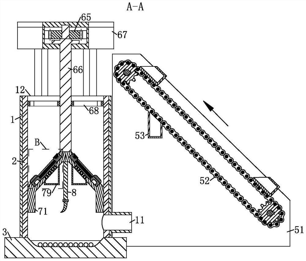
[0036] As an embodiment of the present invention, the inclined end of the distribution plate 71 is provided with a chute 72, and the chute 72 is provided with a No. 1 slider 73 and a No. 2 slider 74. The No. 1 slider 73 and No. 2 slide block 74 are slidably connected with chute 72, wherein No. 1 slide block 73 is located at the upper end of chute 72, No. 2 chute 72 is located at the lower end of chute 72, and between No. 1 chute 72 and No. 2 chute 72 There is a buffer spring 75 fixedly connected between them; when working, it is easy for the waste material to fall too fast and collide with the inner wall of the refractory layer 2, resulting in damage to the refractory layer 2; in order to solve this problem, the present invention is provided with a No. Slide block 73 and No. 2 slide block 74, when waste material falls and collides with No. 1 slide block 73, waste material promotes No. 1 slide block 73 compression buffer spring 75, under the effect of No. 1 slide block 73 and bu...


PUM


Abstract

The invention belongs to the technical field of iron and steel smelting, and particularly relates to an iron and steel metallurgical furnace which comprises a furnace shell, a refractory layer, a base, a controller and a conveying unit, wherein the furnace shell is fixedly connected to the base, and the refractory layer is fixedly connected with the inner wall of the furnace shell; and a discharging port is formed in the side face of the bottom of the furnace shell, and a feeding port is formed in the upper end of the furnace shell. The conveying unit is located on one side of the furnace shell, and fuel is arranged on the base; the controller is arranged on the side face of the base, and used for controlling the iron and steel metallurgical furnace to automatically operate; and a transmission unit and a material distributing unit are arranged on the furnace shell. According to the iron and steel metallurgical furnace, through arrangement of the transmission unit and the material distributing unit on the furnace shell, distribution of steel waste is achieved; through cooperation of the transmission unit and the material distributing unit, the problem that long steel bars are difficult to melt is solved, and the melting efficiency is improved; and the accumulation phenomenon of the waste is relieved.

Description

technical field [0001] The invention belongs to the technical field of iron and steel smelting, in particular to an iron and steel metallurgical furnace. Background technique [0002] Metallurgical furnace is an industrial furnace for thermal processing of various materials or workpieces in the process of metallurgical production. Thermal treatment is a treatment process characterized by the temperature rise of materials or workpieces, such as roasting, smelting, heating, heat treatment, drying, etc. Most of the production links of iron and steel metallurgy and non-ferrous metallurgy are inseparable from furnaces. Historically, the innovation of many production links, the improvement of product output and quality, are closely related to the reform of old metallurgical furnaces and the application of new metallurgical furnaces. The energy consumption of the metallurgical industry depends to a large extent on the energy consumption of various metallurgical furnaces. [0003...

Claims


Application Information

Patent Timeline
Patent Type & Authority Applications(China)
IPC IPC(8): C21C5/56
CPCC21C5/562Y02P10/20
Inventor 陈祥瑞左建军
Owner 陈祥瑞
Learn More